Using PPI to Generate 8MHZ Signal

Hi,

I'm using the PPI component to generate 8MHz GPIO signal. this signal is an input for power amplifier analog RF transmitter.

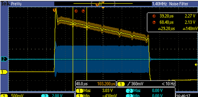
While the digital 8MHz signal looks fine, we are noticing some bumps every 40 us in the RF analog signal. when trying to use the SPI clock to create the 8MHz signal the bumps are eliminated and we get a clean signal.

As the PPI input clock is 16MHz, I was wondering if theoretically its capable to create a digital 8MHz signal? that means that the GPIO should be toggled every single clock, is that an overkill in terms of performance for the PPI or should it be able to handle this task?

The bumps were also reproduced with the DK evaluation board to generate the 8MHz signal, see bump in the image below:
Parents
  • Hello Joshua,

    I'll have to get back to you on this tomorrow.

    You are using the 5340?

    Are these bumps a problem for your application?

    Regards,

    Elfving

  • The slope of it seems even more odd to me, was that somehow intentional from you?

    Are you seeing the same bumps without it being turned off and on this frequently?

    Just noticed that you've added code here in a reply. I'll see if I can reproduce this on my side.

    Regards,

    Elfving

  • Hi,

    the slope is a side-effect of some HW current protection we have, its not a problem for us.

    Thanks 

  • levijo said:

    the slope is a side-effect of some HW current protection we have, its not a problem for us.

    I see. Did you try different frequencies and see if that made the bumps dissapear?

    Would you mind sending me the entire project that reproduces this for you?

    Regards,

    Elfving

  • the following code was isolated from the entire project, and it reproduced the problem. to see the bumps you would have to have our hardware with the RF analog path. We guess that in the digital path it reflects in some jitters or delays but it's hard for us to track with our HW debug tools.

    main.c:

    #include <zephyr/device.h>
    #include <zephyr/drivers/pwm.h>
    #include <zephyr/kernel.h>
    #if defined(CONFIG_CLOCK_CONTROL_NRF)
    #include <zephyr/drivers/clock_control.h>
    #include <zephyr/drivers/clock_control/nrf_clock_control.h>
    #endif /* defined(CONFIG_CLOCK_CONTROL_NRF) */
    #if defined(NRF54L15_XXAA)
    #include <hal/nrf_clock.h>
    #endif /* defined(NRF54L15_XXAA) */
    
    #define LOG_LEVEL CONFIG_LOG_DEFAULT_LEVEL
    #include <zephyr/logging/log.h>
    LOG_MODULE_REGISTER(main);
    
    static const struct pwm_dt_spec pwm_led0 = PWM_DT_SPEC_GET(DT_ALIAS(pwm_led0));
    
    static int clock_init(void);
    static int setup_pwm(void);
    
    int main(void)
    {
    
    #if defined(CONFIG_CLOCK_CONTROL_NRF)
        clock_init();
    #endif
    
        setup_pwm();
    
        while (true) {
            k_sleep(K_MSEC(1000U));
        }
    
        return 0;
    }
    
    #if defined(CONFIG_CLOCK_CONTROL_NRF)
    static int clock_init(void)
    {
        int err;
        int res;
        struct onoff_manager *clk_mgr;
        struct onoff_client clk_cli;
    
        clk_mgr = z_nrf_clock_control_get_onoff(CLOCK_CONTROL_NRF_SUBSYS_HF);
        if (!clk_mgr) {
            LOG_ERR("unable to get the clock manager");
            return -1;
        }
    
        sys_notify_init_spinwait(&clk_cli.notify);
    
        err = onoff_request(clk_mgr, &clk_cli);
        if (err < 0) {
            LOG_ERR("clock request failed (error: %d)", err);
            return -1;
        }
    
        do {
            err = sys_notify_fetch_result(&clk_cli.notify, &res);
            if (!err && res) {
                LOG_ERR("clock could not be started (resone: %d)", res);
                return -1;
            }
        } while (err);
    
    #if defined(NRF54L15_XXAA)
        /* MLTPAN-20 */
        nrf_clock_task_trigger(NRF_CLOCK, NRF_CLOCK_TASK_PLLSTART);
    #endif /* defined(NRF54L15_XXAA) */
    
        LOG_INF("HF clock has started");
    
        return 0;
    }
    #endif /* CONFIG_CLOCK_CONTROL_NRF */
    
    static int setup_pwm(void)
    {
        LOG_INF("set PWM");
    
        if (!pwm_is_ready_dt(&pwm_led0)) {
            LOG_ERR("PWM device %s is not ready", pwm_led0.dev->name);
            return -1;
        }
    
        if (pwm_set_dt(&pwm_led0, PWM_NSEC(125U), PWM_NSEC(63U)) != 0) {
            LOG_ERR("failed to set PWM device %s", pwm_led0.dev->name);
            return -1;
        }
    
        return 0;
    }

    nrf5340dk_cpuapp.overlay:

    / {
    	aliases {
    	};
    };
    
    
    &sw_pwm {
    	status = "okay";
    	channel-gpios = <&gpio1 9 PWM_POLARITY_INVERTED>;
    };
    
    &pwm_led0 {
    	pwms = <& sw_pwm 0 PWM_MSEC(20) PWM_POLARITY_INVERTED>;
    };
    

Reply
  • the following code was isolated from the entire project, and it reproduced the problem. to see the bumps you would have to have our hardware with the RF analog path. We guess that in the digital path it reflects in some jitters or delays but it's hard for us to track with our HW debug tools.

    main.c:

    #include <zephyr/device.h>
    #include <zephyr/drivers/pwm.h>
    #include <zephyr/kernel.h>
    #if defined(CONFIG_CLOCK_CONTROL_NRF)
    #include <zephyr/drivers/clock_control.h>
    #include <zephyr/drivers/clock_control/nrf_clock_control.h>
    #endif /* defined(CONFIG_CLOCK_CONTROL_NRF) */
    #if defined(NRF54L15_XXAA)
    #include <hal/nrf_clock.h>
    #endif /* defined(NRF54L15_XXAA) */
    
    #define LOG_LEVEL CONFIG_LOG_DEFAULT_LEVEL
    #include <zephyr/logging/log.h>
    LOG_MODULE_REGISTER(main);
    
    static const struct pwm_dt_spec pwm_led0 = PWM_DT_SPEC_GET(DT_ALIAS(pwm_led0));
    
    static int clock_init(void);
    static int setup_pwm(void);
    
    int main(void)
    {
    
    #if defined(CONFIG_CLOCK_CONTROL_NRF)
        clock_init();
    #endif
    
        setup_pwm();
    
        while (true) {
            k_sleep(K_MSEC(1000U));
        }
    
        return 0;
    }
    
    #if defined(CONFIG_CLOCK_CONTROL_NRF)
    static int clock_init(void)
    {
        int err;
        int res;
        struct onoff_manager *clk_mgr;
        struct onoff_client clk_cli;
    
        clk_mgr = z_nrf_clock_control_get_onoff(CLOCK_CONTROL_NRF_SUBSYS_HF);
        if (!clk_mgr) {
            LOG_ERR("unable to get the clock manager");
            return -1;
        }
    
        sys_notify_init_spinwait(&clk_cli.notify);
    
        err = onoff_request(clk_mgr, &clk_cli);
        if (err < 0) {
            LOG_ERR("clock request failed (error: %d)", err);
            return -1;
        }
    
        do {
            err = sys_notify_fetch_result(&clk_cli.notify, &res);
            if (!err && res) {
                LOG_ERR("clock could not be started (resone: %d)", res);
                return -1;
            }
        } while (err);
    
    #if defined(NRF54L15_XXAA)
        /* MLTPAN-20 */
        nrf_clock_task_trigger(NRF_CLOCK, NRF_CLOCK_TASK_PLLSTART);
    #endif /* defined(NRF54L15_XXAA) */
    
        LOG_INF("HF clock has started");
    
        return 0;
    }
    #endif /* CONFIG_CLOCK_CONTROL_NRF */
    
    static int setup_pwm(void)
    {
        LOG_INF("set PWM");
    
        if (!pwm_is_ready_dt(&pwm_led0)) {
            LOG_ERR("PWM device %s is not ready", pwm_led0.dev->name);
            return -1;
        }
    
        if (pwm_set_dt(&pwm_led0, PWM_NSEC(125U), PWM_NSEC(63U)) != 0) {
            LOG_ERR("failed to set PWM device %s", pwm_led0.dev->name);
            return -1;
        }
    
        return 0;
    }

    nrf5340dk_cpuapp.overlay:

    / {
    	aliases {
    	};
    };
    
    
    &sw_pwm {
    	status = "okay";
    	channel-gpios = <&gpio1 9 PWM_POLARITY_INVERTED>;
    };
    
    &pwm_led0 {
    	pwms = <& sw_pwm 0 PWM_MSEC(20) PWM_POLARITY_INVERTED>;
    };
    

Children
  • Hi Joshua, 
    HĂĄkon is away this week. There can be some delay. I just want to ask you for some more information in the mean time. You mentioned that  "the digital 8MHz signal looks fine" did you mean that the signal is clean and no jitter ? Or you are suspecting there is jitter but you couldn't verify that using your logic analyzer/oscilloscope ?

    Have you tried to change to another GPIO pin ? Do you have any other activity on the chip, for example using the RADIO or other high frequency peripheral ? My suggestion is to try to reproduce the issue using minimal application. 

     Have you tried to lower the frequency ? If you did and could reproduce the issue, then it can be easier to monitor the signal using logic analyzer/oscilloscope to find if there is any jitter. 

    From my point of view,  the PWM is not really designed to be used as the clock signal for RF communication. 

  • Hi,

    1. the digital signal looks fine, we couldn't find jitters, but we suspect there are some and we can't capture it with our scope, as we managed to get a signal without bumps when using the SPI clock for the 8 MHZ instead of PWM without the bumps, so we suspect there must be some jitters.

    2. we haven't tried to use another GPIO, are there some GPIO's that are more recommended to use than others?

    3. The code I have provided is a minimal code that produces the digital using PPI and PWM, other than that nothing is configured to be enabled, unless there are some peripherals that needs to be shut down actively that I'm not aware of.

    4. We will try to lower the frequency and see if it reproduces

    5. We have managed to configure the PWM with the nRf52 MCU in our previous HW design and it worked fine (Note that our current RF design is not exactly the same), what clock would you recommend using for RF communication? 

  • Hi again, 

    Some GPIO are closer to the radio internally and I was thinking that the radio activity may affect the GPIO. But as you mentioned you reproduced the issue without other peripheral active so it could be something else. It's worth to try on different GPIO pin though. 

    8MHz is about at the maximum limit of PPI&TIMER. Our peripheral is running at 16MHz and in your case it need 2 cycles to toggle up and down the GPIO to generate the clock signal. SPI uses the HFCLK to generate it SCK signal so it's more stable and more reliable from my point of view. 

    Please let us know the result of your tests. 


  • Hi,

    see below some more inputs

    1. we tried a different GPIO, the results are the same - bump occurs in the final signal

    2. we tried using nRF52 instead of nRF53 to the same RF analog input, we get a clean signal with no bumps

    3. When activating the Dmic with nRF53 the output signal have a significantly less bumps (every few seconds instead of every few ms)

  • Hi again Joshua,

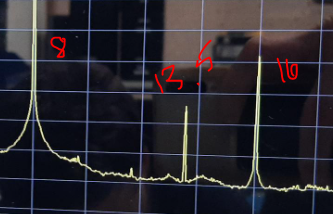
    So the signal from PWM sample you sent me looks ok on the nRF53, though I see that there is some additional jitter there at 13.5Mhz in addition to 8Mhz and 16Mhz for some reason.

    I do not see the same spike on the nRF52. I don't know what that is doing there yet.

    Regards,

    Elfving

Related