nrfjprog --readqspi unreliable

Hello,

I have a custom hardware, with an external 128MB QSPI flash memory connected to a nRF5340. My current task at hand, is to store firmware update images for MCUBoot there. The firmware is stored by the application using a custom driver for the external flash memory.

I've used nrfjprog already, to read measurement data from that external flash memory and that worked quite well. That's why it toke me quite some time to realize, that nrfjprog is doing something stupid here.

The external flash memory has a page size of 4kB and when reading the flash memory content, every first byte of every empty page reads 0x0f instead of 0xff. I changed the operations to be used to a single data line (read_mode = "FASTREAD"; write_mode = "PP") and slowed down the QSPI clock frequency to M2. Attaching a logic analyser, shows, that the flash memory response with 0xff (not 0x0f) to page read request.

Before opening this request, I updated the Segger JLink software to the newest version and then, the next try to read the flash content, showed the correct results! I did an other test and used `

west build --pristine -b"nrf5340dk/nrf5340/cpuapp" --build-dir ./build --sysbuild  .` && `west flash --recover ` to install new firmware on the nRF53. A following read, using nrfjprog showed again, wrong results (0x0f at the begin of every page), while the logic analyser still shows the correct picture.

I power reset, both custom hardware and debugger (J-Trace Pro) but that didn't fixed the issue. Combined with my observation from this ticket (https://devzone.nordicsemi.com/f/nordic-q-a/115570/using-mcuboot-with-nrf5340), that sometimes build errors are not reproducible, my suspicion is, that the `west build` or `west flash` command is changing some configuration data outside of the build folder.

I've used ´nrfjprog` a few month ago and could not find any issues. What changed to the project, was an update to nRF Connect SDK v2.7.99-cs2.

nrfjprog version: 10.24.2 external

JLinkARM.dll version: 8.10d

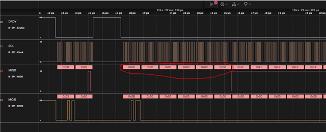
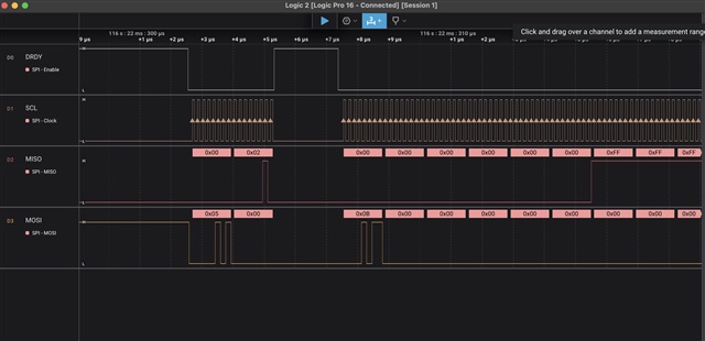
Here, a screen shot of the QSPI trace:

% nrfjprog --readqspi recording.bin --qspiini ./config.toml 
[ #################### ]   0.000s | Reading external memory, 0x200000 bytes @ 0x00000000 - Done                        
Storing data in 'recording.bin'.
% hexdump -C recording.bin | head                           
00000000  0f ff ff ff ff ff ff ff  ff ff ff ff ff ff ff ff  |................|
00000010  ff ff ff ff ff ff ff ff  ff ff ff ff ff ff ff ff  |................|

Attached is the entire trace and the used configuration file.

Best regards

Torsten

Parents
  • Hello,

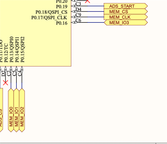
    According to the nRF5340's QSPI documentation, only the dedicated QSPI pins should be used for QSPI:

    https://docs.nordicsemi.com/bundle/ps_nrf5340/page/qspi.html#ariaid-title2

    So it could be that what you are seeing is a result of this. 

    Is it too late to change the GPIOs?

    Best regards,

    Edvin

  • Ok, I understand. 

    Yes, it also states that the configs will not be used in the comment above the QSPI pins. 

    So when changing to normal (non-quad) SPI, and you analyze the pins, and you see the 0xFF using saleae, do you still read 0x0F through the nRF53? Or does the readout change when you are doing these changes?

    What I find a bit strange is the amount of clock ticks before the MISO line goes high:

    And it is a bit difficult to understand whether the first 0xFF is actually referring to the first byte on the page or not. 

    Is it possible to write something to the first flash page:

    0x01 02 03 04 05 06 07 08 09 0a 0b 0c 0d 0e 0f 10 ...

    Something like that, and then you can read it back, to check whether the SPI starts at 01, or if it starts somewhere later?

    Best regards,

    Edvin

  • Hi Edvin,

    Originally, I used read_mode = "READ4O", write_mode = "PP4IO" and frequency = "M16" in the toml file. That resulted (read by nrfjprog) in reading 0x88, 0x88 as the very first two bytes of every page begin of an empty flash memory.

    I changed that settings to the one, that are now in the toml file and nrfjprog started to report these 0x0f bytes at the beginning of every page of an empty flash memory page, while on the logic analyzer trace, clearly 0xff is visible.

    The late start of the MISO line going high, is because, the command on the MOSI line is quite large (0x0b plus 4 times 0x00, as the 32 bit address, plus 8 dummy bits; see 7.25.10 of the nrf5340 data sheet).

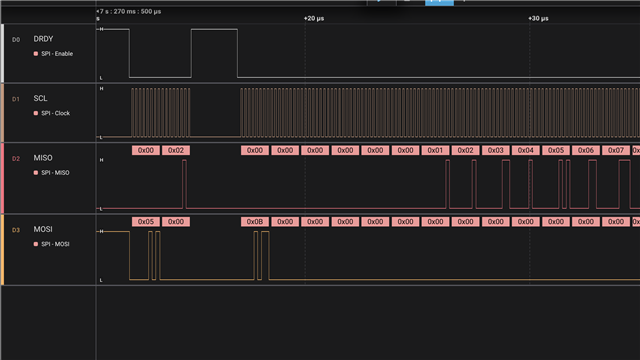
    I wrote a small test program, that erased the first page, and wrote that patter to the beginning of the page:

    static constexpr std::uint8_t pattern[] = {
        0x01, 0x02, 0x03, 0x04, 0x05, 0x06, 0x07, 0x08,
        0x09, 0x0a, 0x0b, 0x0c, 0x0d, 0x0e, 0x0f, 0x10,
        0x00, 0x11, 0x22, 0x33, 0x44, 0x55, 0x66, 0x77,
        0x88, 0x99, 0xaa, 0xbb, 0xcc, 0xdd, 0xee, 0xff
    };
    

    Reading that back from the flash memory, using nrfjprog, yields this pattern:

    00000000  00 10 20 30 40 50 60 70  80 90 a0 b0 c0 d0 e0 f1  |.. 0@P`p........|
    00000010  00 01 12 23 34 45 56 67  78 89 9a ab bc cd de ef  |...#4EVgx.......|
    00000020  ff ff ff ff ff ff ff ff  ff ff ff ff ff ff ff ff  |................|
    *
    

    The traces look like I would expect them (attached in the next messages).

    I think, the most notable data point with this issue is, that it worked _once_ after I've installed the newest version of the JLink software (see above).

    best regards

    Torsten

Reply
  • Hi Edvin,

    Originally, I used read_mode = "READ4O", write_mode = "PP4IO" and frequency = "M16" in the toml file. That resulted (read by nrfjprog) in reading 0x88, 0x88 as the very first two bytes of every page begin of an empty flash memory.

    I changed that settings to the one, that are now in the toml file and nrfjprog started to report these 0x0f bytes at the beginning of every page of an empty flash memory page, while on the logic analyzer trace, clearly 0xff is visible.

    The late start of the MISO line going high, is because, the command on the MOSI line is quite large (0x0b plus 4 times 0x00, as the 32 bit address, plus 8 dummy bits; see 7.25.10 of the nrf5340 data sheet).

    I wrote a small test program, that erased the first page, and wrote that patter to the beginning of the page:

    static constexpr std::uint8_t pattern[] = {
        0x01, 0x02, 0x03, 0x04, 0x05, 0x06, 0x07, 0x08,
        0x09, 0x0a, 0x0b, 0x0c, 0x0d, 0x0e, 0x0f, 0x10,
        0x00, 0x11, 0x22, 0x33, 0x44, 0x55, 0x66, 0x77,
        0x88, 0x99, 0xaa, 0xbb, 0xcc, 0xdd, 0xee, 0xff
    };
    

    Reading that back from the flash memory, using nrfjprog, yields this pattern:

    00000000  00 10 20 30 40 50 60 70  80 90 a0 b0 c0 d0 e0 f1  |.. 0@P`p........|
    00000010  00 01 12 23 34 45 56 67  78 89 9a ab bc cd de ef  |...#4EVgx.......|
    00000020  ff ff ff ff ff ff ff ff  ff ff ff ff ff ff ff ff  |................|
    *
    

    The traces look like I would expect them (attached in the next messages).

    I think, the most notable data point with this issue is, that it worked _once_ after I've installed the newest version of the JLink software (see above).

    best regards

    Torsten

Children
  • Trace is not accepted as being too large. Let me know, if you are interested into the trace, then I would provide you a download link.

  • Torsten Robitzki said:

    Originally, I used read_mode = "READ4O", write_mode = "PP4IO" and frequency = "M16" in the toml file. That resulted (read by nrfjprog) in reading 0x88, 0x88 as the very first two bytes of every page begin of an empty flash memory.

    This sounds very similar to this ticket:
    Problem with QSPI S25FL064L flash memory and 0xEB command

    The solution there was some configuration that is written to the external flash's configuration registers. Perhaps it says somewhere here, but I can't find the name of the external flash chip, and hence, I don't know what datasheet to look for. 

    Can you please specify the flash chip model? And you can try the fix in the ticket in the link if it happens to be the same one, or if you see that it has a different number of dummy bits, other than what we use. 

    Best regards,

    Edvin

  • Hi Edwin,

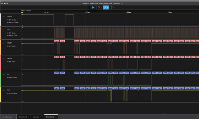
    I tried to boil it down, to an easier to debug problem, by switching to 1 data bit. But ok, I did the same measurements with 4 data bits. The device in question, is the MT25QU01GBBB, a 128MB NOR flash. To address the entire chip, 32 bit addressing is required.

    The expected content of the flash memory is:

    00000000 3d b8 f3 96 00 00 00 00 00 02 00 00 d0 59 0a 00 |=............Y..|
    00000010 04 00 00 00 00 01 2a 00 00 00 00 00 00 00 00 00 |......*.........|
    00000020 ff ff ff ff ff ff ff ff ff ff ff ff ff ff ff ff |................|

    Reading 0xEE, 0xAD, 0x7A, 0x49 from the 4 data lines (see screen shot) on the first 8 (data) clocks would be
    - 0b1110`1110,
    - 0b1010`1101,
    - 0b0100`1001 and
    - 0b0111`1010.

    Expected:
    - 0b0011`1101,
    - 0b1011`1000,
    - 0b1111`0011,
    - 0b1001`0110

    which seems to fit the expectation. If I compare the trace with Figure 134 (32-bit READ4O; SPIMODE = MODE0) of v1.3.1 of the nRF5340 data sheet, they seem to match exatly.

    Now, when reading the flash memory content, with `nrfjprog`:

    % nrfjprog --readqspi recording.bin --qspiini ./config.toml
    % hexdump -C recording.bin | head

    00000000 88 88 3d b8 f3 96 00 00 00 00 00 02 00 00 d0 59 |..=............Y|
    00000010 0a 00 00 00 00 00 00 01 2a 00 00 00 00 00 00 00 |........*.......|

    Wild guess: When I look at figure 135 of the same data sheet, there are just 6 dummy bits. If the peripheral would be configured to expect only 6 dummy bits, and D3 beeing high during the 7th and 8th dummy bit, clocked out by the flash memory, the peripheral would read 0x88, 0x88 during the first 4 clocks cycles.

    All in all, the problem seems to boil down, to the peripheral starting to read in data 4 clock cycles too early (or expecting 4 dummy bits less, than the memory is sending).

    Again, two oberservations / data points, I would like to stress once more:

    • nrfjprog worked for use, before we switched to nRF Connect SDK v2.7.99-cs2.
    • nrfjprog worked exactly once, after I've update the JLink software

    A few more data points:

    • Our application uses a custom driver, that accesses the QSPI peripheral directly. That driver does not has that problem.
    • We use MCUBoot and MCUBoot uses the `official` nordic driver and this combination also shows no problem.

    With all that data points, I really suspect that there is some kind of additional configuration, that `nrfprog` is reading / processing and that this additional configuration, somehow is added / created / introduced by the new `sysbuild` feature.

    best regards

    Torsten

    P.S.: I've just discovered an other "intersting" data point: When I shrink down the size of the configured size of the memory (mem_size = 0x80 in the toml file), the actual access on the QSPI bus takes just a fraction of a second (as expected). However, nrfjprog runs nearly 20s. The reason, why it takes that long, is that nrfjprog writes 3840MB to disk:

    % rm recording.txt
    % ls -la recording.bin
    ls: recording.bin: No such file or directory
    % time nrfjprog --readqspi recording.bin --qspiini ./config.toml
    [ #################### ] 0.000s | Reading external memory, 0x0080 bytes @ 0x00000000 - Done
    Storing data in 'recording.bin'.
    nrfjprog --readqspi recording.bin --qspiini ./config.toml 19,26s user 2,86s system 98% cpu 22,383 total
    % ls -la recording.bin
    -rw-r--r-- 1 todi staff 4026531840 7 Nov 16:29 recording.bin
    % hexdump -C recording.bin
    00000000 88 88 3d b8 f3 96 00 00 00 00 00 02 00 00 d0 59 |..=............Y|
    00000010 0a 00 00 00 00 00 00 01 2a 00 00 00 00 00 00 00 |........*.......|
    00000020 00 00 ff ff ff ff ff ff ff ff ff ff ff ff ff ff |................|
    00000030 ff ff ff ff ff ff ff ff ff ff ff ff ff ff ff ff |................|
    *
    f0000000

    Edit: it's MB, not GB

  • Hello,

    Looking at the datasheet:
    https://www.datasheet4u.com/datasheet-pdf/Micron/MT25QU01GBBB/pdf.php?id=1225539

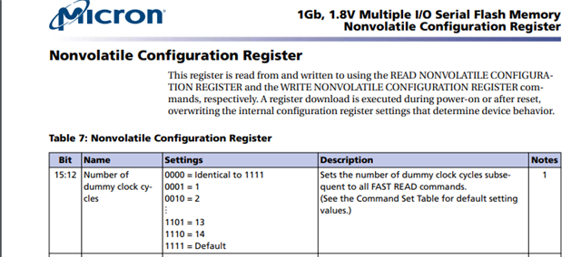
    Page 25:

    Can you please try to set this to 4 (0b0100), and see if that changes the behavior? Since this is non-volatile, it should be sufficient to do this only once. 

    Best regards,

    Edvin

Related