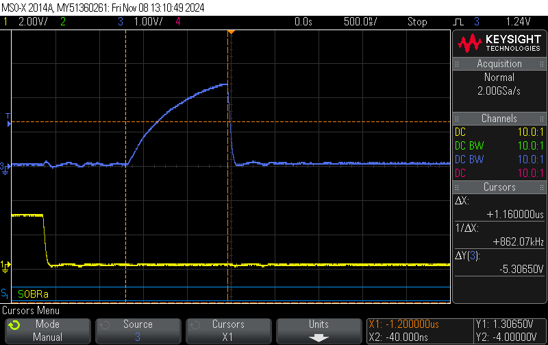
Potential TLDR:
The nRF52 and possibly nRF53 are unusable at 100kHz with targets that require clock stretching and enforce a reasonable minimum clock period. This covers a very broad selection of targets, in particular lot of TI parts included in COTS battery packs.
Context:
nRF52840 on PC10056 dev board operating as an I2C controller with a target that uses clock stretching while operating at "standard speed" (100kHz).
nRF Connect SDK v2.7.0-5cb85570ca43
Dev kit has DETECT (shield detect) pulled low to enable the onboard pull ups.
I note that there are quite a few semi-related previous posts, however the threads contain a lot of conjecture and hand waving. None that I have found really get to the bottom of the issue or have a viable solution.
This issue has come up on pre-production hardware as an intermittent bug, I have replicated it on the dev kit to avoid distraction about hardware. However this is problem in a mature project with considerable NRE behind it.
Issue observed
When reading from the target (and possibly in other transactions) with i2c_write_read_dt() the TWIM occasionally produces a significantly shortened clock pulse after the target stretches the clock. I have observed this in particular on first clock after a stretch, after the controller has sent an ack in response to a byte from the target. I suspect I have seen it elsewhere, however, that was before I appreciated what I was looking at.

The shortened clock is of varying length down to 1.2us, when optimistically measured at the first observable change in the trace. In practice, after considering thresholds for high and low, it ends up in the region of 850ns from the point of view of the target in a practical design.

In this case, the target disregards clock periods under 4us. A feature that mitigates the effect of noise on SCL. Not an unreasonable margin of 20% from the expected 5us clock period.
If there is any doubt about this being a feature, I have seen the lack of this feature in other targets cause no end of headache during compliance testing. An example result being a locked up bus during ESD testing.
It is also of note that even if the bus had no capacitance and the pull ups were magic resulting in no rise time, the clock pulse is still only 1.2us.
Errata:
The only mention of TWIM in the errata document(r3) is errata 219, TWIM: I2C timing spec is violated at 400 kHz. This errata states:
Conditions: Using TWIM at 400 kHz.
It seems very reasonable to consider this errata as not applicable when operating at 100kHz. In fact, on first reading, it appears that 100kHz would be a viable mitigation for problems at 400kHz.
If short clocks are considered an error at 400kHz, resulting in an errata. Surely this would also be considered an error at 100kHz where expectations on valid clock length would be longer. Noting that if the device does not conform to a documented standard (eg I2C) and does not provide full documentation on behaviour, a user can only work from reasonable expectation. The datasheet does not seem to document the minimum clock high period to highlight that it is not as might be expected.
Mitigation:
Working on the principle that this is the issue documented in errata 219 is highly likely to be the same thing, I tested the workaround provided with the FREQUENCY value scaled to match the context of 100kHz. This does not resolve the issue. Even with the clock speed reduced to ~12kHz the TWIM is producing clock pulses at ~1.2uS.
I have looked at using the bit-bang driver in zephyr, it did not work fully, requiring more debugging. Also, the bus is used quite a bit elsewhere in the system so bit-banging is not really an acceptable route to go.
Other parts:
Given that we are strongly tied into the nordic ecosystem with a lot of sunk NRE, we could consider moving to a different part. I note that the nRF5340 errata Rev1 v1.9 contains the same errata, almost word for word as ID47. Presuming that this means it has inherited the same peripheral IP block, including the issue. It seems that moving to the nRF53 will not solve the issue. The nRF54 does not currently have any public documentation.
Conclusion:
The nRF52 and possibly nRF53 is unusable at 100kHz with targets that require clock stretching and enforce a reasonable minimum clock period. This covers a very broad selection of targets, in particular lot of TI parts included in COTS battery packs.
Questions:
1) Is there a mitigation for this other than bit banging or is it simply impossible to use nordic BLE parts for many "I2C" applications?
2) Should the errata not be more clear that it applies (even more so) at standard speed (100kHz).
3) Does this also apply to the nrF53?
4) Has the issue been carried to the nRF54 or is this a potential route out of a corner?
Thanks in advance.
Tom
EDIT: Corrected errata no


