Clarification on SPI Transceive Timing in nRF Connect SDK for RHS2116 Integration

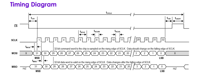
We are developing on the nRF52 Development Kit (nRF52 DK) for the nRF52832 SoC. Our application involves a 4-wire pipelined SPI communication with the Intan RHS2116 chip. According to the RHS2116 documentation (page 30, Picture 1), the SPI connection is configured such that the RHS2116 automatically outputs data two command cycles after a command is sent. This means that by the time we reach the 3rd command, there will be output data on MISO that we need to receive concurrently as the master (nRF52832) transmits the next command via MOSI.

Our challenge is with the nRF Connect SDK and Zephyr OS: specifically, it’s unclear from Zephyr’s SPI library documentation if the spi_transceive function performs read and write operations within the same command cycle, which is required to meet the pipelined data flow of the RHS2116.

Could you confirm if spi_transceive in the nRF Connect SDK supports simultaneous read/write operations in the same cycle? Additionally, if there are configurations or alternative methods recommended for achieving this synchronized SPI communication with the nRF52832, we would appreciate any guidance.

Parents
  • Hi,

    Could you confirm if spi_transceive in the nRF Connect SDK supports simultaneous read/write operations in the same cycle? Additionally, if there are configurations or alternative methods recommended for achieving this synchronized SPI communication with the nRF52832, we would appreciate any guidance.

    SPI is full duplex, ie. that you can receive and transmit in the same transaction. 

    However, the sensor that you link to seems to want two bytes on MOSI, and then it'll return the data on MISO after that, as stated in this page:

    According to the RHS2116 documentation (page 30, Picture 1),

    a “Master Out, Slave In” data line (MOSI) to receive commands from the master device;
    and a “Master In, Slave Out” data line (MISO) to send pipelined results from prior commands to the master device.


    Kind regards,

    Håkon

  • Hi, thanks for the response!

    We’re still seeing error 22, which suggests the SPI module isn’t addressed correctly with the spi_transceive_dt function. It seems like the SPI setup might not be configured right. Any advice on adding a new SPI device properly?

    Specifically:

    1. How to configure the device tree and the device tree overlay to set up a CS pin?
    2. Is a custom .yaml file needed for this particular SPI module, and if so, how should that be structured?

    Here’s our current overlay for the SPI module:

    &spi1 {
           compatible = "nordic,nrf-spi"; // using SPI as per ERRATA 58
           status = "okay";
           pinctrl-0 = <&spi1_default>;
           pinctrl-1 = <&spi1_sleep>;
           pinctrl-names = "default", "sleep";
           cs-gpios = <&gpio0 30 GPIO_ACTIVE_LOW>;
           rhs2116: rhs2116@0 {
                 compatible = "vnd,spi-device"; reg = <0>;
                 spi-max-frequency = <1600000>;
                 label = "rhs2116";
           };
    };
    &pinctrl {
             spi1_default: spi1_default {
                    group1 {
                           psels = <NRF_PSEL(SPIM_SCK, 0, 28)>,
                                       <NRF_PSEL(SPIM_MOSI, 0, 29)>,
                                       <NRF_PSEL(SPIM_MISO, 0, 31)>;
                    };
             };
             spi1_sleep: spi1_sleep {
                      group1 {
                           psels = <NRF_PSEL(SPIM_SCK, 0, 28)>,
                                       <NRF_PSEL(SPIM_MOSI, 0, 29)>,
                                       <NRF_PSEL(SPIM_MISO, 0, 31)>;
                           low-power-enable;
                       };
             };
    };
  • Hi,


    Have you had a look at this section of the ncs dev academy?

    https://academy.nordicsemi.com/courses/nrf-connect-sdk-intermediate/lessons/lesson-5-serial-peripheral-interface-spi/topic/exercise-1-10/


    If you still see an issue, can you please post your code?


    Kind regards,

    Håkon

  • Hi Hakan,

    I am the student currently responsible for the implementation.

    The above error has been solved by removing the node "rhs2116" from the overlay. However I'm still not able to establish communication between our intan module and the nrf52 DK.

    As a reminder the intan rhs2116 asks for 32 bits dataframes per chip select cycle:

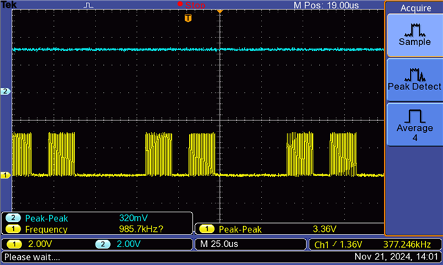
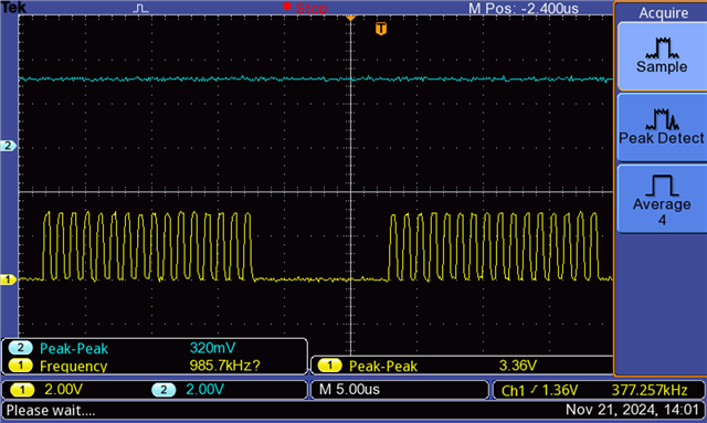
    However after observing the outputs of the nRF 52 dk on an oscilloscope, the sclk seems to have a delay between 16bits cycles, which is unwanted behavior.

    Also the chip select pin doesn't seem to change neither.

    Here's the overlay configuration of the spi bus and buffer configurations:

    &spi1 {        
        compatible = "nordic,nrf-spi";                 // SPI controller, e.g., SPI1
        status = "okay";           // Enable this SPI controller
        pinctrl-0 = <&spi1_default>;
        pinctrl-1 = <&spi1_sleep>;
        pinctrl-names = "default", "sleep";
        cs-gpios = <&gpio0 30 GPIO_ACTIVE_LOW>; // Chip Select pin (CS), active low
        label = "SPI_1";
    };
    
    &pinctrl {
        spi1_default: spi1_default {
            group1 {
                psels = <NRF_PSEL(SPIM_SCK, 0, 28)>,					 
                        <NRF_PSEL(SPIM_MOSI, 0, 29)>,
                        <NRF_PSEL(SPIM_MISO, 0, 31)>;
            };
        };
        spi1_sleep: spi1_sleep {
            group1 {
                psels = <NRF_PSEL(SPIM_SCK, 0, 28)>,
                        <NRF_PSEL(SPIM_MOSI, 0, 29)>,
                        <NRF_PSEL(SPIM_MISO, 0, 31)>;
                low-power-enable;
            };
        };
    };

    spi configs:

    static uint8_t tx_buffer[4];
    static uint8_t rx_buffer[4] = {0x00, 0x00, 0x00, 0x00};
    static uint32_t tx32;
    static uint32_t rx32;
    
    static const struct spi_config spi_cfg = {
    	.operation = SPI_WORD_SET(8) | SPI_TRANSFER_MSB ,
    	.frequency = 1000000, //1MHz
    	.slave = 0,
    };
    
    struct device * spi_dev;
    
    static void spi_init(void)
    {
    	const char* const spiName = "SPI_1";
    	spi_dev = device_get_binding(spiName);
    
    	if (spi_dev == NULL) {
    		printk("Could not get %s device\n", spiName);
    		return;
    	}
    }
    
    const struct spi_buf tx_buf = {
            .buf = tx_buffer,
            .len = sizeof(tx_buffer)
    };
    const struct spi_buf_set tx = {
            .buffers = &tx_buf,
            .count = 1
    };
    
    const struct spi_buf rx_buf = {
            .buf = rx_buffer,
            .len = sizeof(rx_buffer),
    };
    const struct spi_buf_set rx = {
            .buffers = &rx_buf,
            .count = 1
    };

    read register function based on spi_transceive between intan and nrf:

    void rhs_read(uint8_t reg_addr, uint8_t flagU, uint8_t flagM) {
        // Prepare the TX buffer: first 32 bits for the register address, next 32 bits for data
        
    	flagU = 0; //set flags to false for testing
    	flagM = 0;
        
    	tx_buffer[0] = 0b11000000 | flagU << 4 | flagM << 5;
    	tx_buffer[1] = reg_addr;
    	tx_buffer[2] = 0b00000000;
    	tx_buffer[3] = 0b00000000;
    
    	tx32 = tx_buffer[0] << (24) | tx_buffer[1] << (16) | tx_buffer[2] << (8) | tx_buffer[3] ;
    	//printk("tx %x \n",tx32);
    
    	int err;
    
    	err = spi_transceive(spi_dev, &spi_cfg, &tx, &rx);
    	if (err) {
    		printk("read intan error: %d\n", err);
    	} else {
            rx32 = rx_buffer[0] << (24) | rx_buffer[1] << (16) | rx_buffer[2] << (8) | rx_buffer[3];
    		
    	}	
    	err = spi_transceive(spi_dev, &spi_cfg, &tx, &rx);//dummy
    	if (err) {
    		printk("read intan error: %d\n", err);
    	} else {
            rx32 = rx_buffer[0] << (24) | rx_buffer[1] << (16) | rx_buffer[2] << (8) | rx_buffer[3];
    		//printk("it 2\n");
    		//printk("RX recv: %x\n", rx32);
    	}	
    	err = spi_transceive(spi_dev, &spi_cfg, &tx, &rx);//dummy
    	if (err) {
    		//printk("read intan error: %d\n", err);
    	} else {
            rx32 = rx_buffer[0] << (24) | rx_buffer[1] << (16) | rx_buffer[2] << (8) | rx_buffer[3];
    		//printk("it 3\n");
    		//printk("RX recv: %x\n", rx32);
    	}	
    
        
    }

    Sorry for the long post and I hope there's a way to solve this!

    Best regards,

  • Hi,


    Since you are setting up the SPI manually, you will need to provide the .cs pin member manually in your firmware. Here's an example of such:

    https://github.com/nrfconnect/sdk-zephyr/blob/v3.7.99-ncs1/samples/boards/nordic/nrfx_prs/src/main.c#L304-L306


    Where "SPI_DEV_NODE" in your case is DT_NODELABEL(spi1).


    vizheli said:
    the sclk seems to have a delay between 16bits cycles, which is unwanted behavior.

    NRF_SPI is not DMA capable (which NRF_SPIM is), so it will have a delay between each byte.

    I think your issue is related to the /CSN pin, try to implement that, then check CSN/CLK/MOSI/MISO pins with a scope or a logic analyzer to see how they behave afterwards.


    Kind regards,

    Håkon

  • Hi Håkon,

    Manually configurating the CSN pin has solved the issue, and the small timing gaps in sclk doesn't seem to cause problems for data integrity.

    Here's the configuration in full:

    static uint8_t tx_buffer[4];
    static uint8_t rx_buffer[4] = {0x00, 0x00, 0x00, 0x00};
    
    struct device * spi_dev;
    
    static const struct spi_config spi_cfg = {
    	.operation = SPI_WORD_SET(8) | SPI_TRANSFER_MSB ,
    	.frequency = 20000000, //maximum frequency of 25MHz per intan rhs2116 specs
    	.slave = 0,
    	.cs = {
    			.gpio = GPIO_DT_SPEC_GET(SPI_DEV_NODE, cs_gpios),
    			.delay=0,
    		},
    };
    
    
    static void spi_init(void)
    {	
    	const char* const spiName = "SPI_1";
    	spi_dev = device_get_binding(spiName);
    	if (spi_dev == NULL) {
    		printk("Could not get %s device\n", spiName);
    		return;
    	}
    }
    
    const struct spi_buf tx_buf = {
            .buf = tx_buffer,
            .len = sizeof(tx_buffer)
    };
    const struct spi_buf_set tx = {
            .buffers = &tx_buf,
            .count = 1
    };
    
    const struct spi_buf rx_buf = {
            .buf = rx_buffer,
            .len = sizeof(rx_buffer),
    };
    const struct spi_buf_set rx = {
            .buffers = &rx_buf,
            .count = 1
    };

    Overlay:

    &spi1 {        
        compatible = "nordic,nrf-spi";                 // SPI controller, e.g., SPI1
        status = "okay";           // Enable this SPI controller
        pinctrl-0 = <&spi1_default>;
        pinctrl-1 = <&spi1_sleep>;
        pinctrl-names = "default", "sleep";
        cs-gpios = <&gpio0 30 GPIO_ACTIVE_LOW>; // Chip Select pin (CS), active low
        label = "SPI_1";
    
        
    };
    
    &pinctrl {
        spi1_default: spi1_default {
            group1 {
                psels = <NRF_PSEL(SPIM_SCK, 0, 28)>,					 
                        <NRF_PSEL(SPIM_MOSI, 0, 29)>,
                        <NRF_PSEL(SPIM_MISO, 0, 31)>;
            };
        };
        spi1_sleep: spi1_sleep {
            group1 {
                psels = <NRF_PSEL(SPIM_SCK, 0, 28)>,
                        <NRF_PSEL(SPIM_MOSI, 0, 29)>,
                        <NRF_PSEL(SPIM_MISO, 0, 31)>;
                low-power-enable;
            };
        };
    };

    Thank you for your help!

  • Hi,


    vizheli said:
    Manually configurating the CSN pin has solved the issue, and the small timing gaps in sclk doesn't seem to cause problems for data integrity.

    Glad to hear that the issue has been solved!

    vizheli said:
    Thank you for your help!

    Always happy to help out. Hope you have a wonderful day!


    Kind regards,

    Håkon

Reply Children
No Data
Related