How to connect other sensor to nrf9160 (i2c and GPIO)

Hi, 

I want to connect LDC2114 to nRF9160. I write the nrf9160dk_nrf9160_ns.overlay and the astri,ldc2114.yaml. I don't know how to set GPIOs in &i2c1 - ldc2114: ldc2114@2a which are the output pins of LDC2114 and input pins of nRF9160.

/ {
	/* Map the devices to the aliases of the application. */ 
	aliases {	
		ldc-sensor = &ldc2114;
	};
	
};

&i2c1 {
    compatible = "nordic,nrf-twim";
    #address-cells = < 0x1 >;
    #size-cells = < 0x0 >;
    reg = < 0x9000 0x1000 >;
    // clock-frequency = < 0x186a0 >;
    clock-frequency = <I2C_BITRATE_STANDARD>;
    interrupts = < 0x9 0x1 >;
    status = "okay";
    pinctrl-0 = < &i2c1_default >;
    pinctrl-1 = < &i2c1_sleep >;
    pinctrl-names = "default", "sleep";
    ldc2114: ldc2114@2a{
        compatible = "astri,ldc2114";   //binding
        status = "okay";
        reg = < 0x2a >;
        label = "LDC2114";
        gpio-controller;
        #gpio-cells = < 0x2 >;
        intb-gpios = < &gpio0 25 0 >; // LDC2114 INTB pin -> nrf9160 INPUT P0.25
        in0-gpios = < &gpio0 24 0 >;  // LDC2114 OUT0 pin -> nrf9160 INPUT P0.24
        in1-gpios = < &gpio0 23 0 >;  // LDC2114 OUT1 pin -> nrf9160 INPUT P0.23
        in2-gpios = < &gpio0 22 0 >;  // LDC2114 OUT2 pin -> nrf9160 INPUT P0.22
        in3-gpios = < &gpio0 21 0 >;  // LDC2114 OUT3 pin -> nrf9160 INPUT P0.21
    };
};

&i2c2 { 
	status = "disabled";
};

&pinctrl {
	i2c1_default: i2c1_default {
		group1 {
			psels = <NRF_PSEL(TWIM_SDA, 0, 30)>,
				    <NRF_PSEL(TWIM_SCL, 0, 31)>;
		};
	};

	i2c1_sleep: i2c1_sleep {
		group1 {
			psels = <NRF_PSEL(TWIM_SDA, 0, 30)>,
				    <NRF_PSEL(TWIM_SCL, 0, 31)>;
			low-power-enable;
		};
	};
};

# Copyright (c) 2018, Peter Bigot Consulting, LLC
# SPDX-License-Identifier: Apache-2.0

description: Sensor LDC2114

compatible: "astri,ldc2114"

include: [sensor-device.yaml, i2c-device.yaml, gpio-controller.yaml, base.yaml]

properties:
  reg:
    required: true

  #alert-gpios:

  "#gpio-cells":
    const: 2

  intb-gpios:
    type: phandle-array
    description: |
      LDC2114 INTB pin -> nrf9160 INPUT P0.25

  in0-gpios:
    type: phandle-array
    description: |
      LDC2114 OUT0 pin -> nrf9160 INPUT P0.24

  in1-gpios:
    type: phandle-array
    description: |
      LDC2114 OUT1 pin -> nrf9160 INPUT P0.23

  in2-gpios:
    type: phandle-array
    description: |
      LDC2114 OUT2 pin -> nrf9160 INPUT P0.22

  in3-gpios:
    type: phandle-array
    description: |
      LDC2114 OUT3 pin -> nrf9160 INPUT P0.21

gpio-cells:
  - pin
  - flags

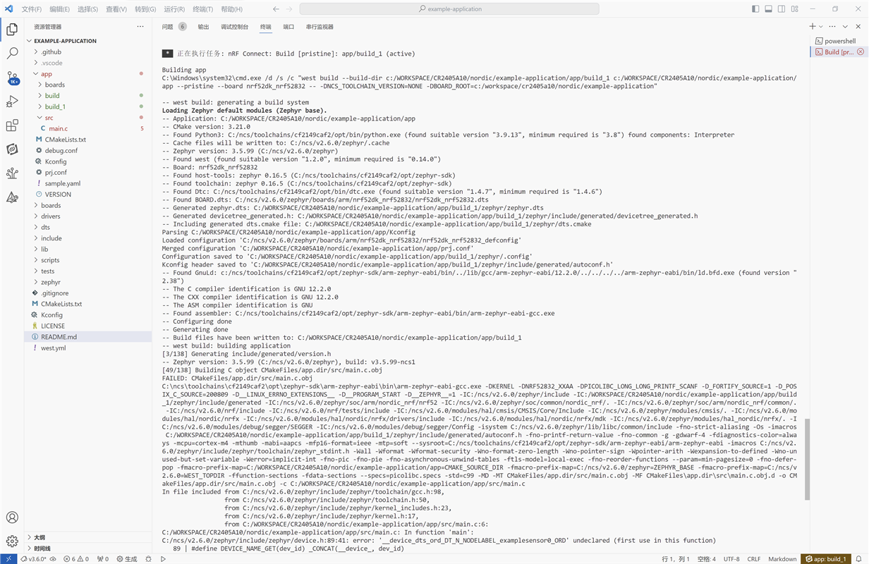
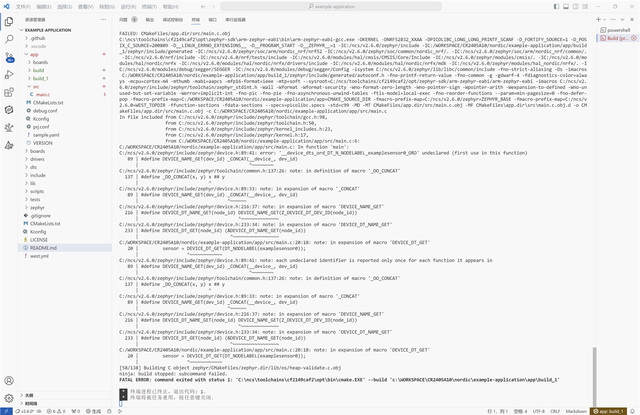
Also, What else should I do in order to connect the devices?

Best regards,

Liza

Parents Reply Children
  • Hi Liza,

    This devacademy course explains how you can use the driver API from your application: https://academy.nordicsemi.com/courses/nrf-connect-sdk-fundamentals/lessons/lesson-6-serial-com-i2c/topic/i2c-driver/.  You can use i2c_write_dt(), or  i2c_write() to set this register on your sensor.

    Best regards,

    Vidar

  • Hi Vidar,

    I use i2c_burst_write() and i2c_burst_read() to write and read value. I write 0x10 to LDC_REG_RESET (reg address 0x0a), but read the value 0 from LDC_REG_RESET (reg address 0x0a). Both two methods return value 0 which indicates that write/read successful.

        error = 1;
        config[0] = 0x10;
        error = i2c_burst_write(dev_i2c,i2c_dt_ldc2114.addr,LDC_REG_RESET,config, sizeof(config));
        if(error != 0){
            printk("LDC_REG_RESET: Failed to write 0x%x to address 0x0%x. \n\r", config[0],LDC_REG_RESET);
        }
        else{
            error = 1;
            printk("LDC_REG_RESET: Successful write 0x%x to address 0x0%x. \n\r", config[0],LDC_REG_RESET);
        }
        printk("size of config=%d\n",sizeof(config));
        printk("1: config[0]=%x\n",config[0]);
    
            k_sleep(K_MSEC(100));
    
            error = i2c_burst_read(dev_i2c,i2c_dt_ldc2114.addr,LDC_REG_RESET,config_read, sizeof(config_read));
            if(error != 0){
                printk("LDC_REG_STATUS: Failed to read data at address 0x0%x. \n\r", LDC_REG_RESET);
            }
            else{
                error = 1;
                printk("LDC_REG_STATUS: Successful read value %x at address 0x0%x. \n\r", config_read[0],LDC_REG_RESET);
            }
        printk("2: config_read[0]=%x\n",config_read[0]);


    output:
    LDC_REG_RESET: Successful write 0x10 to address 0x0a. 
    size of config=1
    1: config[0]=10
    LDC_REG_STATUS: Successful read value 0 at address 0x0a. 
    2: config_read[0]=0

    Thanks,

    Liza

  • Hi Liza,

    I have not worked with this IC before, but I had a look at the datasheet, and it seems like the RESET register is supposed to be 0 after reset. Section 7.3.6 also outlines a special handshake process to perform the write sequence. Have you tried reading the status register instead?

  • Hi Vidar,

    You are right! The RESET register is supposed to be 0 after reset. I read the status register and get what I want.

    But it seems that i2c_burst_write() and i2c_burst_read() have byte limit?

    I try to write 27 bytes buff to LDC_REG_CHAN_EN(0x0c) and the writing error occurs. Then I reduce the buff to 15 bytes, and write & read success.

    ------------------------write 27 bytes to LDC_REG_CHAN_EN (0x0c):--------------------------------------------------
    
    uint8_t configbuf[]={                            0xFF, 0x03, 0x3F, 0x00, //0x0C ~0x0F
                    0x3F, 0x01, 0x3F, 0x07, 0x3F, 0x07, 0x00, 0x02, //0x10 ~0x17
                    0x03, 0x00, 0xff, 0x00, 0xFF, 0x00, 0x00, 0x00, //0x18 ~0x1F
                    0xA7, 0x00, 0xA7, 0x00, 0xA7, 0x00, 0xA7};      //0x20
    uint8_t cfgcomp[32];
    
            k_sleep(K_MSEC(2));
            error = i2c_burst_write(dev_i2c,i2c_dt_ldc2114.addr,LDC_REG_CHAN_EN,configbuf, 27);
            if(error!=0){
                printk("\n--ERROR: LDC_REG_CHAN_EN: Failed to write data at address 0x0%x.-- \n\r", LDC_REG_CHAN_EN);
                return;
            } 
            k_sleep(K_MSEC(2));
            error = i2c_burst_read(dev_i2c,i2c_dt_ldc2114.addr,LDC_REG_CHAN_EN,cfgcomp, 27);
            if(error!=0){
                printk("\n--ERROR: LDC_REG_CHAN_EN: Failed to read data at address 0x0%x.-- \n\r", LDC_REG_CHAN_EN);
                return;
            } 
            for(i=0;i<27;i++){
                printk("configbuf[%d] = %x   ", i, configbuf[i]);
                printk("cfgcomp[%d] = %x\n", i, cfgcomp[i]);
                if(cfgcomp[i] != configbuf[i]){
                    printk("\n--ERROR: LDC_REG_CHAN_EN--\n");
                    //return;
                }
            }
    
    
    ------------------------output:-------------------------------------------
    --ERROR: LDC_REG_CHAN_EN: Failed to write data at address 0x0c.--


    --------------------------After reducing the buff to 15 bytes:------------------------------
    
    uint8_t configbuf[]={                            0xFF, 0x03, 0x3F, 0x00, //0x0C ~0x0F
                    0x3F, 0x01, 0x3F, 0x07, 0x3F, 0x07, 0x00, 0x02, //0x10 ~0x17
                    0x03, 0x00, 0xff, 0x00, 0xFF, 0x00, 0x00, 0x00, //0x18 ~0x1F
                    0xA7, 0x00, 0xA7, 0x00, 0xA7, 0x00, 0xA7};      //0x20
    uint8_t cfgcomp[32];
    
            k_sleep(K_MSEC(2));
            error = i2c_burst_write(dev_i2c,i2c_dt_ldc2114.addr,LDC_REG_CHAN_EN,configbuf, 15);
            if(error!=0){
                printk("\n--ERROR: LDC_REG_CHAN_EN: Failed to write data at address 0x0%x.-- \n\r", LDC_REG_CHAN_EN);
                return;
            } 
            k_sleep(K_MSEC(2));
            error = i2c_burst_read(dev_i2c,i2c_dt_ldc2114.addr,LDC_REG_CHAN_EN,cfgcomp, 15);
            if(error!=0){
                printk("\n--ERROR: LDC_REG_CHAN_EN: Failed to read data at address 0x0%x.-- \n\r", LDC_REG_CHAN_EN);
                return;
            } 
            for(i=0;i<15;i++){
                printk("configbuf[%d] = %x   ", i, configbuf[i]);
                printk("cfgcomp[%d] = %x\n", i, cfgcomp[i]);
                if(cfgcomp[i] != configbuf[i]){
                    printk("\n--ERROR: LDC_REG_CHAN_EN--\n");
                    //return;
                }
            }
    
    
    ------------------output:----------------
    configbuf[0] = ff   cfgcomp[0] = ff
    configbuf[1] = 3   cfgcomp[1] = 3
    configbuf[2] = 3f   cfgcomp[2] = 3f
    configbuf[3] = 0   cfgcomp[3] = 0
    configbuf[4] = 3f   cfgcomp[4] = 3f
    configbuf[5] = 1   cfgcomp[5] = 1
    configbuf[6] = 3f   cfgcomp[6] = 3f
    configbuf[7] = 7   cfgcomp[7] = 7
    configbuf[8] = 3f   cfgcomp[8] = 3f
    configbuf[9] = 7   cfgcomp[9] = 7
    configbuf[10] = 0   cfgcomp[10] = 0
    configbuf[11] = 2   cfgcomp[11] = 2
    configbuf[12] = 3   cfgcomp[12] = 3
    configbuf[13] = 0   cfgcomp[13] = 0
    configbuf[14] = ff   cfgcomp[14] = ff


    So I split the 27 bytes to 12 bytes and 15 bytes, then write and read successfully.

    Thanks,

    Liza

  • Hi Liza,

    You may get more information about why the write failed by enabling CONFIG_LOG to get the logs from the nrfx I2C driver. The TWIM hardware supports sending up to 4096 bytes, but the data may be NACKed by the slave, which will cause the write transaction to be aborted. From the datasheet it seems that the LDC_REG_CHAN_EN register is only 1 byte.

    Best regards,

    Vidar

Related