How to connect other sensor to nrf9160 (i2c and GPIO)

Hi, 

I want to connect LDC2114 to nRF9160. I write the nrf9160dk_nrf9160_ns.overlay and the astri,ldc2114.yaml. I don't know how to set GPIOs in &i2c1 - ldc2114: ldc2114@2a which are the output pins of LDC2114 and input pins of nRF9160.

/ {
	/* Map the devices to the aliases of the application. */ 
	aliases {	
		ldc-sensor = &ldc2114;
	};
	
};

&i2c1 {
    compatible = "nordic,nrf-twim";
    #address-cells = < 0x1 >;
    #size-cells = < 0x0 >;
    reg = < 0x9000 0x1000 >;
    // clock-frequency = < 0x186a0 >;
    clock-frequency = <I2C_BITRATE_STANDARD>;
    interrupts = < 0x9 0x1 >;
    status = "okay";
    pinctrl-0 = < &i2c1_default >;
    pinctrl-1 = < &i2c1_sleep >;
    pinctrl-names = "default", "sleep";
    ldc2114: ldc2114@2a{
        compatible = "astri,ldc2114";   //binding
        status = "okay";
        reg = < 0x2a >;
        label = "LDC2114";
        gpio-controller;
        #gpio-cells = < 0x2 >;
        intb-gpios = < &gpio0 25 0 >; // LDC2114 INTB pin -> nrf9160 INPUT P0.25
        in0-gpios = < &gpio0 24 0 >;  // LDC2114 OUT0 pin -> nrf9160 INPUT P0.24
        in1-gpios = < &gpio0 23 0 >;  // LDC2114 OUT1 pin -> nrf9160 INPUT P0.23
        in2-gpios = < &gpio0 22 0 >;  // LDC2114 OUT2 pin -> nrf9160 INPUT P0.22
        in3-gpios = < &gpio0 21 0 >;  // LDC2114 OUT3 pin -> nrf9160 INPUT P0.21
    };
};

&i2c2 { 
	status = "disabled";
};

&pinctrl {
	i2c1_default: i2c1_default {
		group1 {
			psels = <NRF_PSEL(TWIM_SDA, 0, 30)>,
				    <NRF_PSEL(TWIM_SCL, 0, 31)>;
		};
	};

	i2c1_sleep: i2c1_sleep {
		group1 {
			psels = <NRF_PSEL(TWIM_SDA, 0, 30)>,
				    <NRF_PSEL(TWIM_SCL, 0, 31)>;
			low-power-enable;
		};
	};
};

# Copyright (c) 2018, Peter Bigot Consulting, LLC
# SPDX-License-Identifier: Apache-2.0

description: Sensor LDC2114

compatible: "astri,ldc2114"

include: [sensor-device.yaml, i2c-device.yaml, gpio-controller.yaml, base.yaml]

properties:
  reg:
    required: true

  #alert-gpios:

  "#gpio-cells":
    const: 2

  intb-gpios:
    type: phandle-array
    description: |
      LDC2114 INTB pin -> nrf9160 INPUT P0.25

  in0-gpios:
    type: phandle-array
    description: |
      LDC2114 OUT0 pin -> nrf9160 INPUT P0.24

  in1-gpios:
    type: phandle-array
    description: |
      LDC2114 OUT1 pin -> nrf9160 INPUT P0.23

  in2-gpios:
    type: phandle-array
    description: |
      LDC2114 OUT2 pin -> nrf9160 INPUT P0.22

  in3-gpios:
    type: phandle-array
    description: |
      LDC2114 OUT3 pin -> nrf9160 INPUT P0.21

gpio-cells:
  - pin
  - flags

Also, What else should I do in order to connect the devices?

Best regards,

Liza

Parents Reply Children
  • Hi Liza,

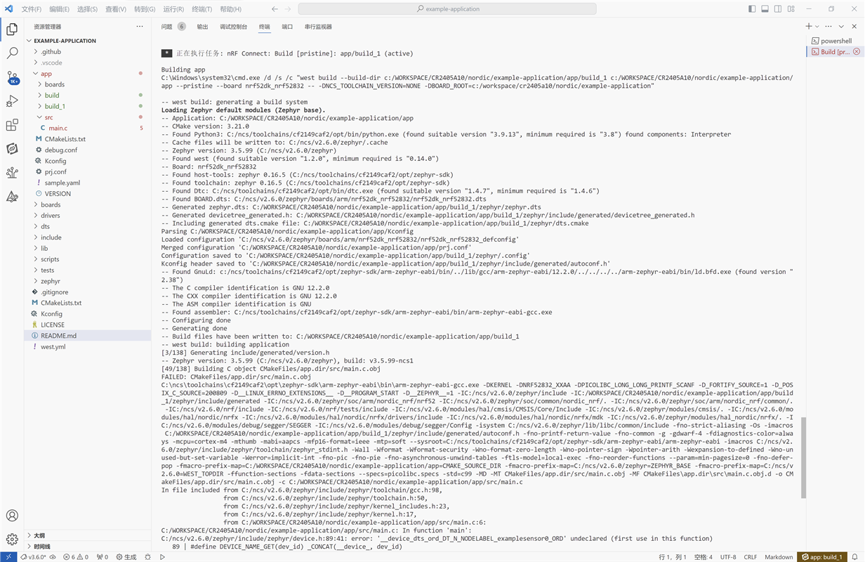
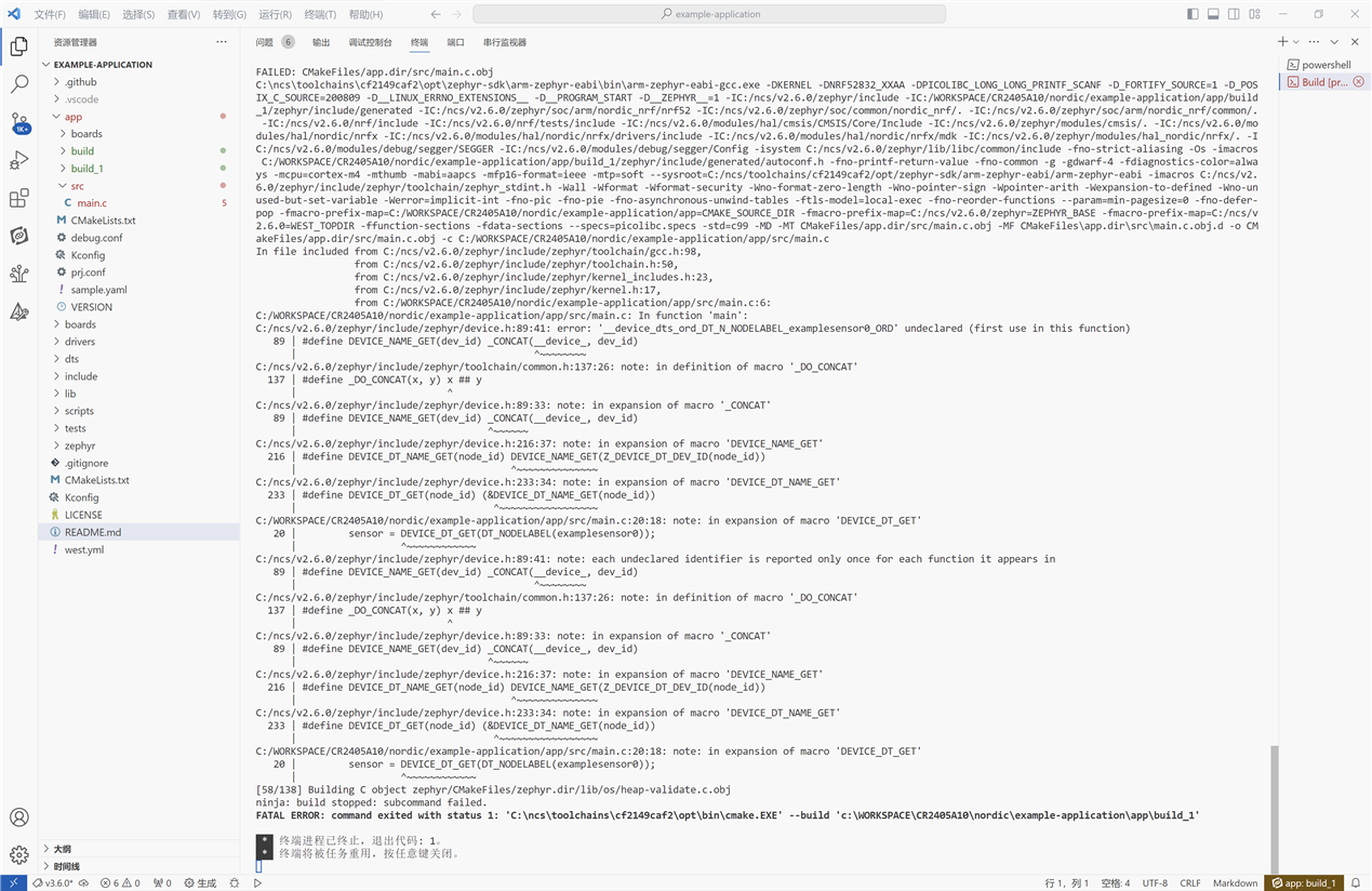
    Do you have a node named 'examplensor0' in your devicetree? You can check by reviewing the generated zephyr.dts file in your build folder. It might be simpler to use the Zephyr I2C API directly in your application instead of creating a new driver based on the Zephyr driver model. I coworker made a sample that does this with the Zephyr SPI driver here: https://github.com/too1/ncs-spi-master-slave-example 

    Best regards,

    Vidar

  • Hi Vidar,

    It's better if I don't need to write driver.

    Do you know how to write data to the register address of LDC2114 through I2C? For example, the LDC2114 address is 0x2a, the output pin polarity can be configured in Register 0x1C.

    Thanks,

    Liza

  • Hi Liza,

    This devacademy course explains how you can use the driver API from your application: https://academy.nordicsemi.com/courses/nrf-connect-sdk-fundamentals/lessons/lesson-6-serial-com-i2c/topic/i2c-driver/.  You can use i2c_write_dt(), or  i2c_write() to set this register on your sensor.

    Best regards,

    Vidar

  • Hi Vidar,

    I use i2c_burst_write() and i2c_burst_read() to write and read value. I write 0x10 to LDC_REG_RESET (reg address 0x0a), but read the value 0 from LDC_REG_RESET (reg address 0x0a). Both two methods return value 0 which indicates that write/read successful.

        error = 1;
        config[0] = 0x10;
        error = i2c_burst_write(dev_i2c,i2c_dt_ldc2114.addr,LDC_REG_RESET,config, sizeof(config));
        if(error != 0){
            printk("LDC_REG_RESET: Failed to write 0x%x to address 0x0%x. \n\r", config[0],LDC_REG_RESET);
        }
        else{
            error = 1;
            printk("LDC_REG_RESET: Successful write 0x%x to address 0x0%x. \n\r", config[0],LDC_REG_RESET);
        }
        printk("size of config=%d\n",sizeof(config));
        printk("1: config[0]=%x\n",config[0]);
    
            k_sleep(K_MSEC(100));
    
            error = i2c_burst_read(dev_i2c,i2c_dt_ldc2114.addr,LDC_REG_RESET,config_read, sizeof(config_read));
            if(error != 0){
                printk("LDC_REG_STATUS: Failed to read data at address 0x0%x. \n\r", LDC_REG_RESET);
            }
            else{
                error = 1;
                printk("LDC_REG_STATUS: Successful read value %x at address 0x0%x. \n\r", config_read[0],LDC_REG_RESET);
            }
        printk("2: config_read[0]=%x\n",config_read[0]);


    output:
    LDC_REG_RESET: Successful write 0x10 to address 0x0a. 
    size of config=1
    1: config[0]=10
    LDC_REG_STATUS: Successful read value 0 at address 0x0a. 
    2: config_read[0]=0

    Thanks,

    Liza

  • Hi Liza,

    I have not worked with this IC before, but I had a look at the datasheet, and it seems like the RESET register is supposed to be 0 after reset. Section 7.3.6 also outlines a special handshake process to perform the write sequence. Have you tried reading the status register instead?

Related