Device tree configuration for SX1261 on a Insight 4520 SIP based on nRF52832

Hello,

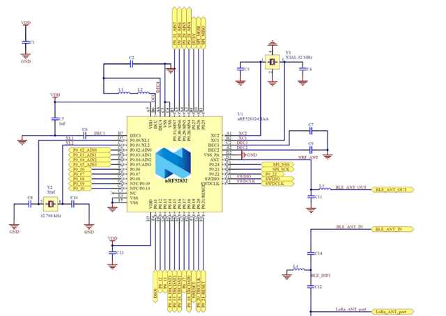
I have a Insight ISP4520 SIp which include a nRF52832 chip and a SX1261 for Lora radio https://www.insightsip.com/products/combo-smart-modules/isp4520
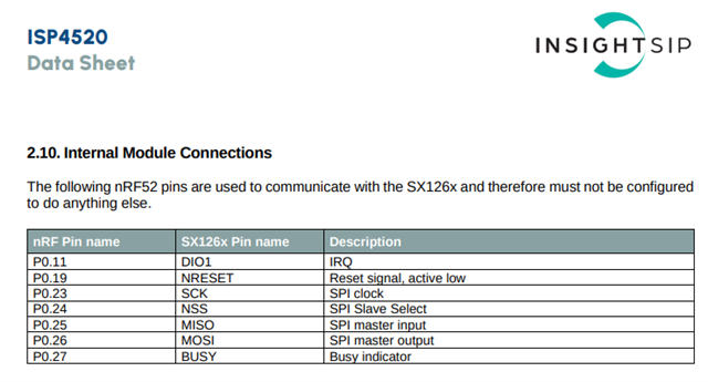
The internal connection of the module are available in this pdf page 13 https://www.insightsip.com/fichiers_insightsip/pdf/ble/ISP4520/isp_lora_DS4520.pdf

I have sucessfully done the nordic academy beginner, BLE and intermediate courses (very interesting) on this chip.

Now I try to make the SX1261 working using this sample https://github.com/zephyrproject-rtos/zephyr/tree/main/samples/drivers/lora/send without success for the moment.

I got this log when running the sample :

[00:00:00.323,364] <dbg> sx126x: sx126x_lora_init: Initializing sx126x
[00:00:00.323,394] <dbg> sx126x: SX126xReset: Resetting radio
[00:00:00.353,576] <dbg> sx126x: SX126xIoIrqInit: Configuring DIO IRQ callback
--- 38 messages dropped ---
[00:00:00.358,795] <dbg> sx126x: SX126xWriteCommand: Issuing opcode 0x8b w. 4 bytes of data
[00:00:00.358,917] <dbg> sx126x: SX126xWriteCommand: Issuing opcode 0x8c w. 6 bytes of data
[00:00:00.359,069] <dbg> sx126x: SX126xReadRegisters: Reading 1 registers @ 0x889
[00:00:00.359,222] <dbg> sx126x: SX126xReadRegisters: register_value
                                 00                                               |.                
[00:00:00.359,222] <dbg> sx126x: SX126xWriteRegisters: Writing 1 registers @ 0x889: 0x4 , ...
[00:00:00.359,344] <dbg> sx126x: SX126xSetRfTxPower: power: 4
[00:00:00.359,375] <dbg> sx126x: SX126xWriteCommand: Issuing opcode 0x95 w. 4 bytes of data
[00:00:00.359,497] <dbg> sx126x: SX126xWriteCommand: Issuing opcode 0x8e w. 2 bytes of data
[00:00:00.359,619] <dbg> sx126x: SX126xWriteCommand: Issuing opcode 0x8a w. 1 bytes of data
[00:00:00.359,710] <dbg> sx126x: SX126xWriteRegisters: Writing 1 registers @ 0x740: 0x14 , ...
[00:00:00.359,832] <dbg> sx126x: SX126xWriteRegisters: Writing 1 registers @ 0x741: 0x24 , ...
[00:00:00.359,954] <dbg> sx126x: SX126xAntSwOff: No antenna switch configured
[00:00:00.359,985] <dbg> sx126x: SX126xWriteCommand: Issuing opcode 0x84 w. 1 bytes of data
[00:00:00.360,137] <dbg> sx126x: SX126xSetOperatingMode: SetOperatingMode: SLEEP (0)
[00:00:00.362,243] <dbg> sx126x: SX126xWriteCommand: Issuing opcode 0x8c w. 6 bytes of data
[00:00:00.362,274] <dbg> sx126x: SX126xWakeup: Sending GET_STATUS
[00:00:00.362,335] <dbg> sx126x: SX126xWakeup: Waiting for device...
[00:00:00.362,365] <dbg> sx126x: SX126xWakeup: Device ready
[00:00:00.362,396] <dbg> sx126x: SX126xAntSwOn: No antenna switch configured
[00:00:00.362,548] <dbg> sx126x: SX126xWriteCommand: Issuing opcode 0x8 w. 8 bytes of data
[00:00:00.362,701] <dbg> sx126x: SX126xWriteCommand: Issuing opcode 0x8c w. 6 bytes of data
[00:00:00.362,854] <dbg> sx126x: SX126xWriteBuffer: Writing buffers @ 0x0 (10 bytes)
[00:00:00.363,037] <dbg> sx126x: SX126xSetOperatingMode: SetOperatingMode: TX (4)
[00:00:00.363,067] <dbg> sx126x: SX126xWriteCommand: Issuing opcode 0x83 w. 3 bytes of data
[00:00:00.363,220] <dbg> sx12xx_common: sx12xx_lora_send: Expected air time of 10 bytes = 289ms
[00:00:00.941,314] <err> sx12xx_common: Packet transmission failed!
[00:00:00.941,345] <dbg> sx126x: SX126xAntSwOff: No antenna switch configured
[00:00:00.941,375] <dbg> sx126x: SX126xWriteCommand: Issuing opcode 0x84 w. 1 bytes of data
[00:00:00.941,497] <dbg> sx126x: SX126xSetOperatingMode: SetOperatingMode: SLEEP (0)
[00:00:00.943,572] <err> lora_send: LoRa send failed

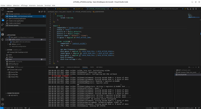
Here is the device tree I tried to configure for the Lora0 device :

/ {
    aliases {
        lora0 = &lora0;
    };
};

&spi1 {
    compatible = "nordic,nrf-spi"; 
    status = "okay";
    pinctrl-0 = <&spi1_default>;
    pinctrl-1 = <&spi1_sleep>;
    pinctrl-names = "default", "sleep";
    cs-gpios = <&gpio0 24 GPIO_ACTIVE_LOW>;

    lora0: sx1261@0 {
    	compatible = "semtech,sx1261";
    	reg = <0>;

        spi-max-frequency = <1000000>; 
        dio1-gpios = <&gpio0 11 (GPIO_PUSH_PULL | GPIO_ACTIVE_HIGH)>;
        reset-gpios = <&gpio0 19 (GPIO_PUSH_PULL | GPIO_ACTIVE_LOW)>;
        busy-gpios = <&gpio0 27 (GPIO_PUSH_PULL | GPIO_ACTIVE_HIGH)>;
        dio2-tx-enable;
        dio3-tcxo-voltage = <7>;
    };
};

And the pinctrl :

&pinctrl {
    spi1_default: spi1_default {
        group1 {
            psels = <NRF_PSEL(SPIM_SCK, 0, 23)>,					 
                    <NRF_PSEL(SPIM_MOSI, 0, 26)>,
                    <NRF_PSEL(SPIM_MISO, 0, 25)>;
        };
    };
    spi1_sleep: spi1_sleep {
        group1 {
            psels = <NRF_PSEL(SPIM_SCK, 0, 23)>,
                    <NRF_PSEL(SPIM_MOSI, 0, 26)>,
                    <NRF_PSEL(SPIM_MISO, 0, 25)>;
            low-power-enable;
        };
    };
};

What is wrong with my device tree configuration ? And why I can use the the SPI0 ?

Many thanks by adavance and feel free to ask more details if needed.

Parents
  • Hi Vincent

    Which version of NCS are you using? Just by looking at the log I can't see anything that stands out in the devicetree, however I think you need to add the antenna-enable-gipo as seen in the semtech sx1262 shield  

    I will see if I can find any lora radio and try to replicate it on my part. 

    Regards

    Runar

  • Sorry for forgtotting the NCS version : I'm using the latest v2.8.0

    Here is a screenshot of my VS code window where you can see it is v2.8.0 :

    The SIP manufacturer (Insight) has a Github repo with some samples but they use the previous NCS version (v1.x.x) without using devicetree. 
    Please have a look to their repo here : https://github.com/insightsip/ISP4520-examples

    I also asked the manufacturer (french company) if they have the devicetree configuration for their SIP because they are the most placed people to write it due to the fact they are the deisgners of the SIP.

    I'm gonna have a look to the overlay you mentionned in your post.

    Thanks for your help !

  • Thanks! As insight has not updated in a while I would rather have a look at the zephyr sample, however I would use the same pins as insight used in their overlay. 

    Regards

    Runar

  • Just an quick update: I did a quick test with the same sample and a sx1262 shield as I linked below and everything worked out of the box. So I suspect following the overlay from the shield will fix it for you

    Regards

    Runar

  • Hi, 

    Thanks for this update, which is good to know.

    I reviewed all the overlay using the one from the s1262 shield and trying to match with the samples from Insight (which use code for configuration dans not and overlay) and one of the difference is there is no antenna enable GPIO on my SIP.

    I'm gonna continue to investigate the code and Insight samples.

    Here is my log of the lora_send sample if you want to compare with yours :

    [00:00:00.323,181] <dbg> sx126x: sx126x_lora_init: Initializing sx126x
    [00:00:00.330,444] <dbg> sx126x: SX126xReset: Resetting radio
    [00:00:00.367,034] <dbg> sx126x: SX126xIoIrqInit: Configuring DIO IRQ callback
    [00:00:00.374,969] <dbg> sx126x: SX126xWakeup: Sending GET_STATUS
    [00:00:00.381,805] <dbg> sx126x: SX126xWakeup: Waiting for device...
    [00:00:00.388,854] <dbg> sx126x: SX126xWakeup: Device ready
    [00:00:00.395,111] <dbg> sx126x: SX126xWriteCommand: Issuing opcode 0x80 w. 1 bytes of data
    [00:00:00.405,364] <dbg> sx126x: SX126xSetOperatingMode: SetOperatingMode: STDBY_RC (1)
    [00:00:00.414,123] <dbg> sx126x: SX126xIoTcxoInit: TCXO on DIO3
    [00:00:00.420,745] <dbg> sx126x: SX126xWriteCommand: Issuing opcode 0x97 w. 4 bytes of data
    [00:00:00.430,999] <dbg> sx126x: SX126xWriteCommand: Issuing opcode 0x89 w. 1 bytes of data
    [00:00:00.446,594] <dbg> sx126x: SX126xIoRfSwitchInit: Configuring DIO2
    [00:00:00.453,918] <dbg> sx126x: SX126xWriteCommand: Issuing opcode 0x9d w. 1 bytes of data
    [00:00:00.479,187] <dbg> sx126x: SX126xSetOperatingMode: SetOperatingMode: STDBY_RC (1)
    [00:00:00.487,945] <dbg> sx126x: SX126xWriteCommand: Issuing opcode 0x80 w. 1 bytes of data
    [00:00:00.498,168] <dbg> sx126x: SX126xSetOperatingMode: SetOperatingMode: STDBY_RC (1)
    [00:00:00.506,927] <dbg> sx126x: SX126xWriteCommand: Issuing opcode 0x96 w. 1 bytes of data
    [00:00:00.517,150] <dbg> sx126x: SX126xWriteCommand: Issuing opcode 0x8f w. 2 bytes of data
    [00:00:00.527,404] <dbg> sx126x: SX126xWriteCommand: Issuing opcode 0x95 w. 4 bytes of data
    [00:00:00.537,658] <dbg> sx126x: SX126xWriteCommand: Issuing opcode 0x8e w. 2 bytes of data
    [00:00:00.547,912] <dbg> sx126x: SX126xWriteCommand: Issuing opcode 0x8 w. 8 bytes of data
    [00:00:00.557,006] <dbg> sx126x: SX126xReadRegisters: Reading 9 registers @ 0x29f
    [00:00:00.565,277] <dbg> sx126x: SX126xReadRegisters: register_value
                                     00 fb 83 27 ba 0e bb e9  1c                      |...'.... .       
    [00:00:00.581,817] <dbg> sx126x: SX126xWriteRegisters: Writing 9 registers @ 0x29f: 0x1 , ...
    [00:00:00.591,186] <dbg> sx126x: SX126xReadRegisters: Reading 9 registers @ 0x29f
    [00:00:00.599,456] <dbg> sx126x: SX126xReadRegisters: register_value
                                     01 08 ac 27 ba 0e bb e9  1c                      |...'.... .       
    [00:00:00.615,997] <dbg> sx126x: SX126xWriteRegisters: Writing 9 registers @ 0x29f: 0x2 , ...
    [00:00:00.625,366] <dbg> sx126x: SX126xAntSwOff: No antenna switch configured
    [00:00:00.633,209] <dbg> sx126x: SX126xWriteCommand: Issuing opcode 0x84 w. 1 bytes of data
    [00:00:00.642,364] <dbg> sx126x: SX126xSetOperatingMode: SetOperatingMode: SLEEP (0)
    *** Booting nRF Connect SDK v2.8.0-a2386bfc8401 ***
    *** Using Zephyr OS v3.7.99-0bc3393fb112 ***
    [00:00:00.661,773] <dbg> sx126x: SX126xWriteCommand: Issuing opcode 0x98 w. 2 bytes of data
    [00:00:00.670,898] <dbg> sx126x: SX126xWakeup: Sending GET_STATUS
    [00:00:00.677,673] <dbg> sx126x: SX126xWakeup: Waiting for device...
    [00:00:00.684,722] <dbg> sx126x: SX126xWakeup: Device ready
    [00:00:00.690,948] <dbg> sx126x: SX126xAntSwOn: No antenna switch configured
    [00:00:00.703,002] <dbg> sx126x: SX126xWriteCommand: Issuing opcode 0x86 w. 4 bytes of data
    [00:00:00.713,226] <dbg> sx126x: SX126xWriteCommand: Issuing opcode 0x80 w. 1 bytes of data
    [00:00:00.723,449] <dbg> sx126x: SX126xSetOperatingMode: SetOperatingMode: STDBY_RC (1)
    [00:00:00.732,208] <dbg> sx126x: SX126xWriteCommand: Issuing opcode 0x8a w. 1 bytes of data
    [00:00:00.742,431] <dbg> sx126x: SX126xWriteCommand: Issuing opcode 0x8b w. 4 bytes of data
    [00:00:00.752,655] <dbg> sx126x: SX126xWriteCommand: Issuing opcode 0x8c w. 6 bytes of data
    [00:00:00.762,908] <dbg> sx126x: SX126xReadRegisters: Reading 1 registers @ 0x889
    [00:00:00.771,148] <dbg> sx126x: SX126xReadRegisters: register_value
                                     04                                               |.                
    [00:00:00.787,628] <dbg> sx126x: SX126xWriteRegisters: Writing 1 registers @ 0x889: 0x4 , ...
    [00:00:00.796,966] <dbg> sx126x: SX126xSetRfTxPower: power: 4
    [00:00:00.803,375] <dbg> sx126x: SX126xWriteCommand: Issuing opcode 0x95 w. 4 bytes of data
    [00:00:00.813,629] <dbg> sx126x: SX126xWriteCommand: Issuing opcode 0x8e w. 2 bytes of data
    [00:00:00.823,852] <dbg> sx126x: SX126xWriteCommand: Issuing opcode 0x8a w. 1 bytes of data
    [00:00:00.834,075] <dbg> sx126x: SX126xWriteRegisters: Writing 1 registers @ 0x740: 0x34 , ...
    [00:00:00.843,536] <dbg> sx126x: SX126xWriteRegisters: Writing 1 registers @ 0x741: 0x44 , ...
    [00:00:00.852,966] <dbg> sx126x: SX126xAntSwOff: No antenna switch configured
    [00:00:00.860,809] <dbg> sx126x: SX126xWriteCommand: Issuing opcode 0x84 w. 1 bytes of data
    [00:00:00.869,964] <dbg> sx126x: SX126xSetOperatingMode: SetOperatingMode: SLEEP (0)
    [00:00:00.880,523] <dbg> sx126x: SX126xWriteCommand: Issuing opcode 0x8c w. 6 bytes of data
    [00:00:00.889,648] <dbg> sx126x: SX126xWakeup: Sending GET_STATUS
    [00:00:00.896,423] <dbg> sx126x: SX126xWakeup: Waiting for device...
    [00:00:00.903,472] <dbg> sx126x: SX126xWakeup: Device ready
    [00:00:00.909,698] <dbg> sx126x: SX126xAntSwOn: No antenna switch configured
    [00:00:00.918,579] <dbg> sx126x: SX126xWriteCommand: Issuing opcode 0x8 w. 8 bytes of data
    [00:00:00.927,673] <dbg> sx126x: SX126xWriteCommand: Issuing opcode 0x8c w. 6 bytes of data
    [00:00:00.937,927] <dbg> sx126x: SX126xWriteBuffer: Writing buffers @ 0x0 (10 bytes)
    [00:00:00.946,472] <dbg> sx126x: SX126xSetOperatingMode: SetOperatingMode: TX (4)
    [00:00:00.954,711] <dbg> sx126x: SX126xWriteCommand: Issuing opcode 0x83 w. 3 bytes of data
    [00:00:00.967,102] <dbg> sx12xx_common: sx12xx_lora_send: Expected air time of 10 bytes = 42ms
    [00:00:01.007,354] <dbg> sx126x: sx126x_dio1_irq_work_handler: Processing DIO1 interrupt
    [00:00:01.016,204] <dbg> sx126x: SX126xReadCommand: Issuing opcode 0x12 (data size: 2)
    [00:00:01.024,902] <dbg> sx126x: SX126xReadCommand: -> status: 0xac
    [00:00:01.031,860] <dbg> sx126x: SX126xWriteCommand: Issuing opcode 0x2 w. 2 bytes of data
    [00:00:01.040,924] <dbg> sx126x: SX126xSetOperatingMode: SetOperatingMode: STDBY_RC (1)
    [00:00:01.049,682] <dbg> sx126x: SX126xAntSwOff: No antenna switch configured
    [00:00:01.057,556] <dbg> sx126x: SX126xWriteCommand: Issuing opcode 0x84 w. 1 bytes of data
    [00:00:01.066,711] <dbg> sx126x: SX126xSetOperatingMode: SetOperatingMode: SLEEP (0)
    [00:00:01.075,195] <err> sx12xx_common: Packet transmission failed!
    [00:00:01.082,427] <err> lora_send: LoRa send failed
    

    Here is the devicetree I wrote for the SIP to compare with yours if possible.insight4520_nrf52832.dtsinsight4520_nrf52832-pinctrl.dtsi

    Defconfig :

    # Enable MPU
    CONFIG_ARM_MPU=y
    
    # Enable hardware stack protection
    CONFIG_HW_STACK_PROTECTION=y
    
    # Enable RTT
    CONFIG_USE_SEGGER_RTT=y
    
    # enable GPIO
    CONFIG_GPIO=y
    
    # enable uart driver
    CONFIG_SERIAL=y
    
    # enable console
    CONFIG_CONSOLE=y
    CONFIG_UART_CONSOLE=y
    

    I also tried to do a TXVW with this code but it didn't work (no continuous wave on my spectrum analyzer showed up) :

    LOG_DBG("TXCW");
    ret = lora_test_cw(lora_dev, 868100000, 14, 10);
    if (ret < 0) {
    	LOG_ERR("LoRa test CW failed");
    	return 0;
    }
    
    k_sleep(K_SECONDS(11));
    LOG_DBG("TXCW done");

    Can you share your overlay and logs please ? This can be useful to compare with mine.

    Thanks !

  • Hi 
    Here's the overlay from my compiled code. As I used the shield I did not have to do anything regarding the overlay

    		spi2: arduino_spi: spi@40023000 {
    			compatible = "nordic,nrf-spi";
    			#address-cells = < 0x1 >;
    			#size-cells = < 0x0 >;
    			reg = < 0x40023000 0x1000 >;
    			interrupts = < 0x23 0x1 >;
    			max-frequency = < 0x7a1200 >;
    			easydma-maxcnt-bits = < 0x8 >;
    			status = "okay";
    			cs-gpios = < &arduino_header 0xd 0x1 >;
    			pinctrl-0 = < &spi2_default >;
    			pinctrl-1 = < &spi2_sleep >;
    			pinctrl-names = "default", "sleep";
    			lora_semtech_sx1262mb2das: sx1262@0 {
    				compatible = "semtech,sx1262";
    				reg = < 0x0 >;
    				spi-max-frequency = < 0xf42400 >;
    				label = "SX1262";
    				reset-gpios = < &arduino_header 0x0 0x1 >;
    				busy-gpios = < &arduino_header 0x9 0x0 >;
    				antenna-enable-gpios = < &arduino_header 0xe 0x0 >;
    				dio1-gpios = < &arduino_header 0xb 0x0 >;
    				dio2-tx-enable;
    				tcxo-power-startup-delay-ms = < 0x5 >;
    			};

    The log itself is nothing interesting at all really 

    *** Booting nRF Connect SDK v2.8.0-a2386bfc8401 ***
    *** Using Zephyr OS v3.7.99-0bc3393fb112 ***
    [00:00:00.810,699] <inf> lora_send: Data sent!
    [00:00:02.105,773] <inf> lora_send: Data sent!
    [00:00:03.400,817] <inf> lora_send: Data sent!
    [00:00:04.695,861] <inf> lora_send: Data sent!
    [00:00:05.990,905] <inf> lora_send: Data sent!
    [00:00:07.285,949] <inf> lora_send: Data sent!
    [00:00:08.580,993] <inf> lora_send: Data sent!
    

    Something just hit me. Do you use external LF crystal or the internal one? All our DK's have external crystals which is set in the config for the DK. If you don't have one you need to add 

    CONFIG_CLOCK_CONTROL_NRF_K32SRC_RC=y
    Regards
    Runar
  • There is 2 crystals on SIP : 

    - Y1 is 32 Mhz 
    - Y2 is 32.768 kHz 

    So I think the Kconfig symbol CONFIG_CLOCK_CONTROL_NRF_K32SRC_RC is not required in my case.

Reply Children
Related