I am attempting to get the SMP server sample to work on some custom hardware in order to run a BLE FOTA. I'm using NCS version 2.6.1.
I'm able to build the SMP server sample successfully using both versions of the custom hardware DTS.
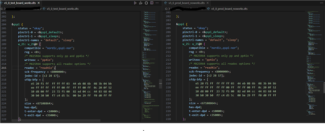
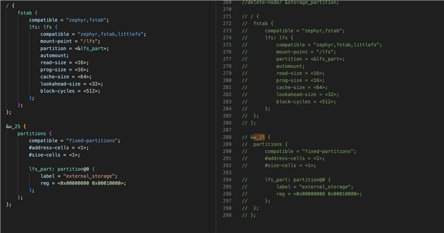
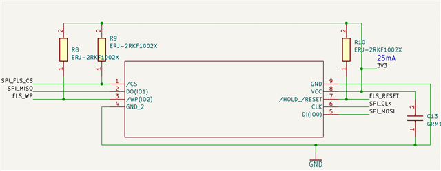
When I comment out the QSPI device on the DTS file for the custom hardware, and flash the merged.hex file using the debugger, the bootloader and application both work as expected. Uploading a new image and testing/confirming also works as expected, with the new firmware running.
However, adding the QSPI device to the DTS causes the same process to fail - flashing merged.hex using the debugger seems to result in no boot. I tried reviewing the partition manager section in the FOTA devacademy lesson, but I'm still not sure what the issue is here.
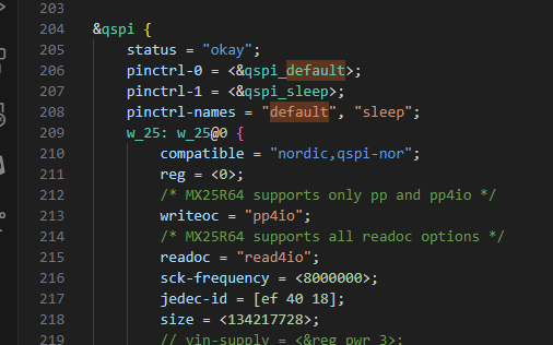
Attached are the two DTS files. The v5_0_test_board.dts is the one that works and has some sections commented. the v5_0_prod_board.dts has these sections uncommented. The setting for the Winbond flash chip use some of the defaults from the mxr flash chip that comes on the devkit - these are eventually going to be corrected, but I don't believe they should affect anything until mcuboot tries to store an image on the external flash, is this correct?
Thanks in advance for the help.