Adding MCUBOOT and QSPI device to DTS causes no boot

I am attempting to get the SMP server sample to work on some custom hardware in order to run a BLE FOTA. I'm using NCS version 2.6.1.

I'm able to build the SMP server sample successfully using both versions of the custom hardware DTS.

When I comment out the QSPI device on the DTS file for the custom hardware, and flash the merged.hex file using the debugger, the bootloader and application both work as expected. Uploading a new image and testing/confirming also works as expected, with the new firmware running.

However, adding the QSPI device to the DTS causes the same process to fail - flashing merged.hex using the debugger seems to result in no boot. I tried reviewing the partition manager section in the FOTA devacademy lesson, but I'm still not sure what the issue is here.

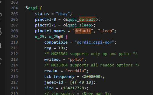
Attached are the two DTS files. The v5_0_test_board.dts is the one that works and has some sections commented. the v5_0_prod_board.dts has these sections uncommented. The setting for the Winbond flash chip use some of the defaults from the mxr flash chip that comes on the devkit - these are eventually going to be corrected, but I don't believe they should affect anything until mcuboot tries to store an image on the external flash, is this correct?

Thanks in advance for the help.

v5_0_prod_board.dtsv5_0_test_board.dts

  • frankenboom said:
    - I must reset the board while manually applying voltage to the rail powering the flash chip - it appears that, even though the vin-supply is added to the DT, whatever driver(?) is active in the bootloader does NOT enable the regulator. I consistently need to manually apply power to the flash chip's VDD in order for the application to run. Is there a way to make sure that the bootloader enables the regulator before attempting any flash transactions? What about for the QSPI driver, which does not have this property?

    If you have an external regulator, you would have to power this in the bootloader before you get access to the flash chip. I had a chat with one of our hardware engineers and we concluded we might need a schematic to answer this. Could you either upload it here if you're comfortable with uploading it publicly or create a new private case and refer to this case as a reference with the schematic?

    Kind regards,
    Andreas

  • Hi Andreas,

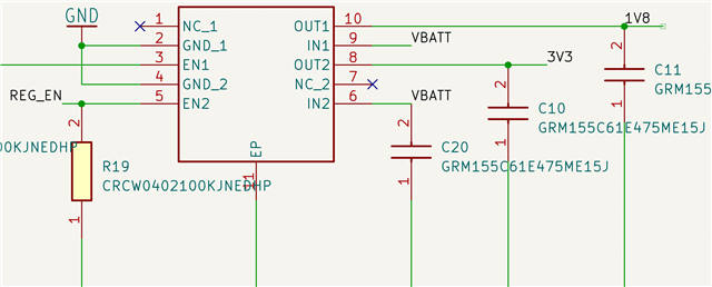
    I can provide some snippets. Generally speaking, the regulator is always connected to the battery. The 3v3 rail is then enabled with a GPIO.

    Here you can see REG_EN net (pulled down) connected to EN2, which controls OUT2, which is the 3v3 rail.

    We are using a FANSTEL BC840M as the module. Pin 26 (on the NRF SOC) controls REG_EN.

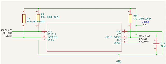
    Here is the flash chip. VCC pin is connected to 3V3 output of the regulator. Note that the pullups for CS, Write protect/IO2, and RESET/IO3 are connected to this same rail.

    After a bit more digging, it sounds like a method mentioned in this ticket may he helpful?
    devzone.nordicsemi.com/.../mcuboot-hold-gpio-on-boot

  • Update: adding CONFIG_REGULATOR=y to the mcuboot child image .conf appears to have fixed the issue with the flash chip not having power before communication is attempted - the board now boots without manual intervention.

    It seems the remaining issue is to experiment with transitioning to QSPI.

  • Hi,

    Looks to me that CONFIG_REGULARTOR=y is what you needed. Glad to hear that!

    W.r.t transitioning to QSPI, which GPIOs had you set your peripheral up to use? More specifically: which GPIOs are qspi_default and qspi_sleep set up to use through pinctrl-0 and 1?

    Kind regards,
    Andreas

Related