Externally power Thingy:91 without battery

Hi,

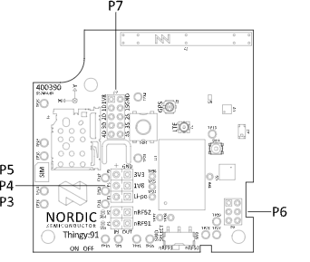
I’m exploring options to externally power the Thingy:91 while isolating it from the battery. I noticed that the board offers three external supply points: P3, P4 and P5. Could you advise on which one would be more appropriate for stable operation, especially for temperature data transfer to cloud?

Additionally, what’s the best way to establish the external power connection? Would placing a jumper in the designated holes suffice, or is there a specific process or configuration to follow?

Lastly, is there a practical way to disable battery power without physically disconnecting it? The battery is mounted inside a hard plastic enclosure, making manual removal quite difficult.

I’d appreciate your guidance on these points. Thank you!

Parents
  • Hi,

    There's no direct way of disconnecting the battery without removing it. There are solder bridges that can be cut to disconnect the nRF9160 and the nRF52840 from the outputs of the onboard PMIC, but these are indented for measuring the current draw of the two devices independent of the rest of the circuit.

    There is 3 voltage rails on the Thingy:91:

    • VSYS: which powers the nRF9160, it's the VSYS output of the ADP5360 PMIC, which is tied to the battery voltage.
    • 3.3V which powers the RF frontend, LEDs, buzzer and color sensor.
    • 1.8V which powers the nRF52840, accelerometers and the pressure/humidity/temperature/gas sensor.

    All of these must be supplied for the thingy to function properly.  My recommendation for powering the Thingy:91 externally is to remove the battery, as use P3 to supply the input of the PMIC with 3.7V, and let the it regulate the 1.8V and 3.3V lines.

    If you want to have a closer look at the schematic you can find the full design files for the Thingy:91 here:

    https://nsscprodmedia.blob.core.windows.net/prod/software-and-other-downloads/dev-kits/thingy91/hardware-files/thingy91---hardware-files-1_6_0.zip

    Best regards,

    Bendik

Reply
  • Hi,

    There's no direct way of disconnecting the battery without removing it. There are solder bridges that can be cut to disconnect the nRF9160 and the nRF52840 from the outputs of the onboard PMIC, but these are indented for measuring the current draw of the two devices independent of the rest of the circuit.

    There is 3 voltage rails on the Thingy:91:

    • VSYS: which powers the nRF9160, it's the VSYS output of the ADP5360 PMIC, which is tied to the battery voltage.
    • 3.3V which powers the RF frontend, LEDs, buzzer and color sensor.
    • 1.8V which powers the nRF52840, accelerometers and the pressure/humidity/temperature/gas sensor.

    All of these must be supplied for the thingy to function properly.  My recommendation for powering the Thingy:91 externally is to remove the battery, as use P3 to supply the input of the PMIC with 3.7V, and let the it regulate the 1.8V and 3.3V lines.

    If you want to have a closer look at the schematic you can find the full design files for the Thingy:91 here:

    https://nsscprodmedia.blob.core.windows.net/prod/software-and-other-downloads/dev-kits/thingy91/hardware-files/thingy91---hardware-files-1_6_0.zip

    Best regards,

    Bendik

Children
  • Hi,

    Following the suggestion, I disconnected the battery from the board (connected via a JST 3-pin wire) and supplied a 3.7V DC source through the P3 port. While monitoring the current consumed by the board, I noticed fluctuations between 5 mA and 30 mA. However, I expected the board to use higher current, with noticeable spikes if it were functioning as intended.

    I’m using this module to log temperature readings to Microsoft Azure Cloud, but the board remained unresponsive, cycling through this 5 mA to 30 mA range without taking any action.

    Thinking the board might require a 3-terminal input (similar to the JST 3-pin battery connection), I removed the small PCB attached to the battery (I’m unclear on the purpose of this PCB—please see the attached photo for reference). I then directly connected the two battery terminals to the DC source, but the issue persisted, and it just used an almost constant current of around 20 mA.

    Interestingly, when I reconnected the battery, the module resumed its normal operation, successfully logging temperature readings to the cloud.

    This behavior is puzzling, as I’m unsure if I made an error in the connection process or if there’s a different approach I should try. Could you clarify why the P3 port did not function as expected, why connecting the DC source to the battery port didn’t work, and whether there's a specific way to connect the DC source to ensure proper operation?

    Looking forward to your insights.

    Thanks, 

    Roshan

Related