Working devicetree for ST7789v display

I have several of these 135x240 display modules that work effortlessly with all of my development platforms, all except for nRF Connect of course.

ST7789v 135x240 1.14" display module

I can't even get Zephyr's bare minimum display driver sample to work after a week of struggle. Note that I've had easy success with the ubiquitous SSD1306 display module, so I'm not completely clueless, but I've hit a brick wall with this ST7789v.

Zephyr's generic ST7789v driver only offers two variations, neither of which match this hardware, so I've tried copying the relevant devicetree settings from other in-tree boards that seemingly share the same panel (such as the M5StickC Plus), but still no success.

Details:

I'm using the nRF5340 Audio DK which is fixed at 1v8, so I'm correctly level-shifting the SPI signals to 3v3 for the display module, and I'm using the appropriate Arduino SPI header pins on the DK for the connections, with the backlight directly tied to 3v3 and always on.

I've edited the in-tree st7789v_waveshare_240x240.overlay file in an attempt to match the hardware, and then added the following line to CMakeLists.txt:

set(SHIELD st7789v_waveshare_240x240)

There are no compilation or runtime errors, and according to the debug log the driver is continually writing to the SPI bus, but while the backlight is clearly on, the display remains blank:

ST7789v display remains blank

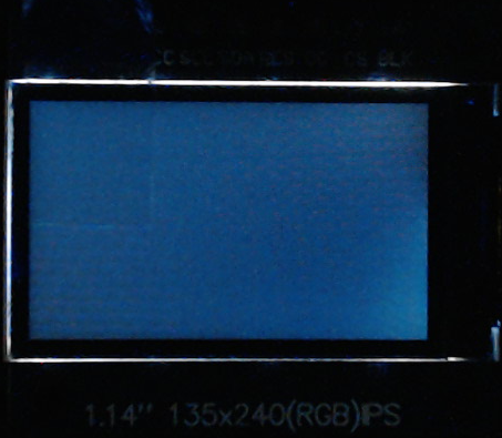
Again, this exact technique worked as expected for the I2C SSD1306, so I'm assuming that my SHIELD overlay is still incorrect, which I've included below:

/ {
	chosen {
		zephyr,display = &st7789v_st7789v_waveshare_240x240;
	};
};

&arduino_spi {
	status = "okay";
	cs-gpios = <&arduino_header 16 GPIO_ACTIVE_LOW>;            /* D10 */

	st7789v_st7789v_waveshare_240x240: st7789v@0 {
		compatible = "sitronix,st7789v";
		spi-max-frequency = <20000000>;
		reg = <0>;
		cmd-data-gpios = <&arduino_header 15 GPIO_ACTIVE_LOW>;  /* D9 */
		reset-gpios = <&arduino_header 14 GPIO_ACTIVE_LOW>;     /* D8 */
		width = <135>;    // width = <240>;
		height = <240>;   // height = <240>;
		x-offset = <53>;  // x-offset = <0>;
		y-offset = <40>;  // y-offset = <0>;
		vcom = <0x28>;    // vcom = <0x19>;
		gctrl = <0x35>;
		vrhs = <0x10>;    // vrhs = <0x12>;
		vdvs = <0x20>;
		mdac = <0x00>;
		gamma = <0x01>;
		colmod = <0x55>;  // colmod = <0x05>;
		lcm = <0x2c>;
		porch-param = [0c 0c 00 33 33];
		cmd2en-param = [5a 69 02 00];  // cmd2en-param = [5a 69 02 01];
		pwctrl1-param = [a4 a1];
		pvgam-param = [d0 00 02 07 0a 28 32 44 42 06 0e 12 14 17];  // pvgam-param = [D0 04 0D 11 13 2B 3F 54 4C 18 0D 0B 1F 23];
		nvgam-param = [d0 00 02 07 0a 28 31 54 47 0e 1c 17 1b 1e];  // nvgam-param = [D0 04 0C 11 13 2C 3F 44 51 2F 1F 1F 20 23];
		ram-param = [00 F0];
		rgb-param = [40 02 14];  // rgb-param = [CD 08 14];
	};
};

Does anyone have a working devicetree for this display that they can share, or an example I could study? I've exhausted every combination of settings I can think of, but cannot find the correct configuration. I don't need the obscene overhead of LVGL, just a functioning driver.

Minutia:

  • nRF Connect SDK/toolchain v2.7.0
  • nRF5340 Audio DK (PCA10121 v1.0.0)
  • VS Code and Plugins (latest 2024-12-02)
  • Hello, 

    My initial search in DevZone gave me the following guide:LVGL on a TFT LCD Display with the nRF9160 DKDid you see this? Here we show how to use the ST7789 on an nRF9160DK.

    Note that the drivers to this display is not provided by Nordic Semiconductor but the Zephyr Project community. 

    From the migration notes of v3.7.0 of the Zephyr OS it states about display

    ST7789V based displays now use the MIPI DBI driver class. These displays must now be declared within a MIPI DBI driver wrapper device, which will manage interfacing with the display. (GitHub #73750) Note that the cmd-data-gpios pin has changed polarity with this update, to align better with the new dc-gpios name.

    /* Legacy ST7789V display definition */
    &spi0 {
        st7789: st7789@0 {
            compatible = "sitronix,st7789v";
            reg = <0>;
            spi-max-frequency = <32000000>;
            reset-gpios = <&gpio0 6 GPIO_ACTIVE_LOW>;
            cmd-data-gpios = <&gpio0 12 GPIO_ACTIVE_LOW>;
            ...
        };
    };
    
    /* New display definition with MIPI DBI device */
    
    #include <zephyr/dt-bindings/mipi_dbi/mipi_dbi.h>
    
    ...
    
    mipi_dbi {
        compatible = "zephyr,mipi-dbi-spi";
        reset-gpios = <&gpio0 6 GPIO_ACTIVE_LOW>;
        dc-gpios = <&gpio0 12 GPIO_ACTIVE_HIGH>;
        spi-dev = <&spi0>;
        #address-cells = <1>;
        #size-cells = <0>;
    
        st7789: st7789@0 {
            compatible = "sitronix,st7789v";
            reg = <0>;
            mipi-max-frequency = <32000000>;
            mipi-mode = <MIPI_DBI_MODE_SPI_4WIRE>;
            ...
        };
    };
    

    If this does not help, I suggest reaching out to the Zephyr Community on Discord.

    Kind regards,
    Øyvind

  • ace.johnny said:
    I've already scoured DevZone and GitHub for answers (I only asked for help because I'm stumped), and have studied both the guide you mentioned, along with one for the SSD1306 as well.

    I fully agree with you with regards to getting the SSD1306 up and running. The ST7789 should be as straight forward when using the Zephyr drivers. I do not currently have this display, but am looking internally for one. 

    Assuming that you are using same the SPI pins as the SSD1306?

    ace.johnny said:
    Please note, as I previously stated, that I'm on NCS v2.7.0 (Zephyr v3.6), so the MIPI wrapper advice is not applicable. I'm well aware of the instability and breaking changes in NCS v2.8.0 (Zephyr 3.7), which is why I'm still waiting for the dust to settle.

    Yeah, it was a long shot, hoping that it might be something there to use. 

    What board are you building for?

    I'm using the nRF5340 Audio DK which is fixed at 1v8, so I'm correctly level-shifting the SPI signals to 3v3 for the display module, and I'm using the appropriate Arduino SPI header pins on the DK for the connections, with the backlight directly tied to 3v3 and always on.

    Have you measured the pins and verified the VDD? Do you have access to a logic analyzer to view the signal coming on the configured GPIOs? 

    Could you share the SSD1306 application that works for you? 

    Thanks!

    Kind regards,
    Øyvind

  • ace.johnny said:
    As per my original post, I'm working from the Zephyr Display Driver sample.

    Understood, the reason for why I ask it to look at the configurations that you've added to prj.conf. As the sample zephyr\samples\drivers\display\ does not include many configurations. 

    ace.johnny said:
    The only difference being that I connected to (and level-shifted) the DK's Arduino I2C header pins.

    There is a difference in regards to I2C vs SPI, and as you point out the need for a level shifter. 

    Have you verified that the correct signals on the SPI lines? 

    A colleague of mine does have an ST7789v and tested with his nRF5340DK

    / {
        chosen {
            zephyr,display = &st7789v_ips_240x240;
        };
    };
     
    &arduino_spi {
        status = "okay";
        cs-gpios = <&arduino_header 16 GPIO_ACTIVE_LOW>;    /* D10 */
     
        st7789v_ips_240x240: st7789v@0 {
            compatible = "sitronix,st7789v";
            spi-max-frequency = <20000000>;
            reg = <0>;
            cmd-data-gpios = <&arduino_header 15 GPIO_ACTIVE_LOW>;  /* D9 */
            reset-gpios = <&arduino_header 14 GPIO_ACTIVE_LOW>; /* D8 */
            width = <240>;
            height = <240>;
            x-offset = <0>;
            y-offset = <0>;
            vcom = <0x19>;
            gctrl = <0x35>;
            vrhs = <0x12>;
            vdvs = <0x20>;
            mdac = <0x00>;
            gamma = <0x01>;
            colmod = <0x05>;
            lcm = <0x2c>;
            porch-param = [0c 0c 00 33 33];
            cmd2en-param = [5a 69 02 01];
            pwctrl1-param = [a4 a1];
            pvgam-param = [D0 04 0D 11 13 2B 3F 54 4C 18 0D 0B 1F 23];
            nvgam-param = [D0 04 0C 11 13 2C 3F 44 51 2F 1F 1F 20 23];
            ram-param = [00 F0];
            rgb-param = [CD 08 14];
        };
    };

    This is lvgl example built for nrf5340dk_nrf5340_cpuapp_ns.overlay and with the following configurations in prj.conf

    CONFIG_LV_Z_MEM_POOL_NUMBER_BLOCKS=8
    CONFIG_MAIN_STACK_SIZE=2048
     
    CONFIG_DISPLAY=y
    CONFIG_DISPLAY_LOG_LEVEL_ERR=y
     
    CONFIG_LOG=y
     
    CONFIG_LVGL=y
    CONFIG_LV_MEM_CUSTOM=y
    CONFIG_LV_USE_LOG=y
    CONFIG_LV_USE_LABEL=y
    CONFIG_LV_USE_BTN=y
    CONFIG_LV_USE_IMG=y
    CONFIG_LV_FONT_MONTSERRAT_14=y
     
    # SPI ST7789
    CONFIG_ST7789V=y
    CONFIG_ST7789V_RGB565=y
     
    # ST7789 Settings for LVGL
    CONFIG_LV_Z_BITS_PER_PIXEL=16
    CONFIG_LV_COLOR_DEPTH_16=y
    CONFIG_LV_COLOR_16_SWAP=y

    Have a look at this .pdf as well: nRF5340_5F00_Display1.3.pdf

    I hope this helps. 


    Kind regards,
    Øyvind

  • Thank you for acknowledging the approach of eliminating variables—it’s often a necessary step in troubleshooting setups like this. That said, I understand that you’ve already taken several key steps and verified many aspects of the configuration yourself.

    I ask again

    Øyvind said:
    Have you measured the pins and verified the VDD? Do you have access to a logic analyzer to view the signal coming on the configured GPIOs? 

    and 

    Øyvind said:
    Have you verified that the correct signals on the SPI lines? 

    Thanks.

  • I'm sorry that we could not provide the correct solution for a very specific board. 

    Kind regards,

    Øyvind

Related