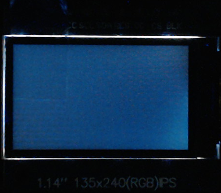
I have several of these 135x240 display modules that work effortlessly with all of my development platforms, all except for nRF Connect of course.

I can't even get Zephyr's bare minimum display driver sample to work after a week of struggle. Note that I've had easy success with the ubiquitous SSD1306 display module, so I'm not completely clueless, but I've hit a brick wall with this ST7789v.
Zephyr's generic ST7789v driver only offers two variations, neither of which match this hardware, so I've tried copying the relevant devicetree settings from other in-tree boards that seemingly share the same panel (such as the M5StickC Plus), but still no success.
Details:
I'm using the nRF5340 Audio DK which is fixed at 1v8, so I'm correctly level-shifting the SPI signals to 3v3 for the display module, and I'm using the appropriate Arduino SPI header pins on the DK for the connections, with the backlight directly tied to 3v3 and always on.
I've edited the in-tree st7789v_waveshare_240x240.overlay file in an attempt to match the hardware, and then added the following line to CMakeLists.txt:
set(SHIELD st7789v_waveshare_240x240)
There are no compilation or runtime errors, and according to the debug log the driver is continually writing to the SPI bus, but while the backlight is clearly on, the display remains blank:

Again, this exact technique worked as expected for the I2C SSD1306, so I'm assuming that my SHIELD overlay is still incorrect, which I've included below:
/ {
	chosen {
		zephyr,display = &st7789v_st7789v_waveshare_240x240;
	};
};

&arduino_spi {
	status = "okay";
	cs-gpios = <&arduino_header 16 GPIO_ACTIVE_LOW>;            /* D10 */

	st7789v_st7789v_waveshare_240x240: st7789v@0 {
		compatible = "sitronix,st7789v";
		spi-max-frequency = <20000000>;
		reg = <0>;
		cmd-data-gpios = <&arduino_header 15 GPIO_ACTIVE_LOW>;  /* D9 */
		reset-gpios = <&arduino_header 14 GPIO_ACTIVE_LOW>;     /* D8 */
		width = <135>;    // width = <240>;
		height = <240>;   // height = <240>;
		x-offset = <53>;  // x-offset = <0>;
		y-offset = <40>;  // y-offset = <0>;
		vcom = <0x28>;    // vcom = <0x19>;
		gctrl = <0x35>;
		vrhs = <0x10>;    // vrhs = <0x12>;
		vdvs = <0x20>;
		mdac = <0x00>;
		gamma = <0x01>;
		colmod = <0x55>;  // colmod = <0x05>;
		lcm = <0x2c>;
		porch-param = [0c 0c 00 33 33];
		cmd2en-param = [5a 69 02 00];  // cmd2en-param = [5a 69 02 01];
		pwctrl1-param = [a4 a1];
		pvgam-param = [d0 00 02 07 0a 28 32 44 42 06 0e 12 14 17];  // pvgam-param = [D0 04 0D 11 13 2B 3F 54 4C 18 0D 0B 1F 23];
		nvgam-param = [d0 00 02 07 0a 28 31 54 47 0e 1c 17 1b 1e];  // nvgam-param = [D0 04 0C 11 13 2C 3F 44 51 2F 1F 1F 20 23];
		ram-param = [00 F0];
		rgb-param = [40 02 14];  // rgb-param = [CD 08 14];
	};
};
Does anyone have a working devicetree for this display that they can share, or an example I could study? I've exhausted every combination of settings I can think of, but cannot find the correct configuration. I don't need the obscene overhead of LVGL, just a functioning driver.
Minutia:
- nRF Connect SDK/toolchain v2.7.0
- nRF5340 Audio DK (PCA10121 v1.0.0)
- VS Code and Plugins (latest 2024-12-02)
