Hello,
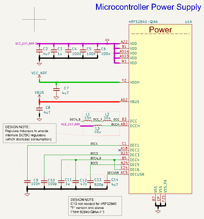
I'm using an nRF52840 on a custom board operating in high voltage mode, powered either by a LiPo battery or USB. The design follows configuration 4 from the nRF52840 reference designs.
To optimize current consumption, I’ve populated inductors for the REG0 and REG1 stages to enable the corresponding DC/DC converters. While enabling the second-stage DC/DC regulator (via NRF_POWER->DCDCEN = 1) successfully reduces current consumption, enabling the first-stage regulator (via NRF_POWER->DCDCEN0 = 1) unexpectedly increases it. I assumed that enabling both DC/DC regulators would provide the best efficiency, but my measurements suggest otherwise. Using an LDO for the first stage and a DC/DC for the second stage seems to yield the best results. Is this behavior expected?
Here are the average current consumption measurements for my application (wake-up for radio, then sleep) , taken using a PPK2 :
At VIN = 3.5V:
- LDO for REG0 and REG1: 126 µA
- DC/DC for REG0, LDO for REG1: 140 µA
- LDO for REG0, DC/DC for REG1: 75 µA
- DC/DC for REG0 and REG1: 97 µA
At VIN = 5V (USB):
- LDO for REG0 and REG1: 135 µA
- DC/DC for REG0, LDO for REG1: 142 µA
- LDO for REG0, DC/DC for REG1: 88 µA
- DC/DC for REG0 and REG1: 105 µA
Additionally, I’ve configured the REGOUT0 register to set VDD at 3V.
Thank you for your help.
Regards,