When detecting low battery voltage using LPCOMP and ADC, the detection voltage changes (occurs approximately 5%)

HI

We are mass producing products using nRF52832.

However, during production, a PCB was found to not detect low battery voltage for about 5%, so we are inquiring about it during review.

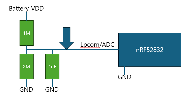
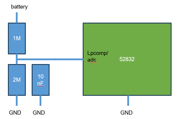
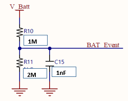
1-1) The circuit configuration is as follows.

1-2) SW configuration is as follows.

- Basic LPCOMP settings -> LPCOMP event occurs -> Switch to ADC to read battery voltage -> When below the reference voltage, LED display
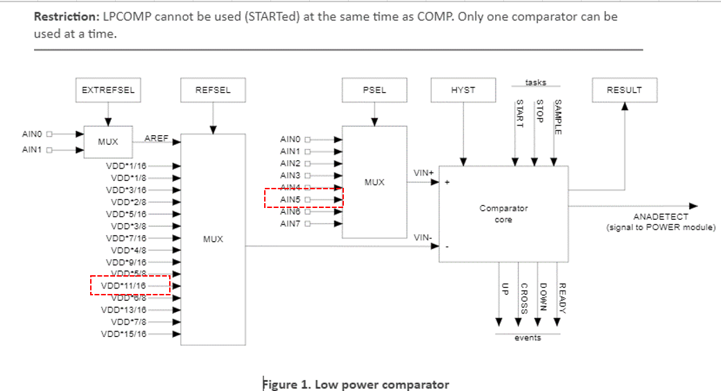
- LPCOMP

static void lpcomp_event_handler(nrf_lpcomp_event_t event)
{
    uint8_t bsp = 0;
    if (event == NRF_LPCOMP_EVENT_DOWN)
    {
       
        //voltage_falls_detected++;
        //voltage_falls_total++;
        
        if( getlpcomp_chceck() == 0 )
        {
           bsp =  getBsp_led_indication_stage(); 
           if( ( bsp == BSP_INDICATE_IDLE ) || ( bsp == BSP_INDICATE_CONNECTED_OFF ) || ( bsp == BSP_INDICATE_USER_STATE_OFF ) )
           {
                bsp_indication_set( BSP_INDICATE_USER_STATE_BAT_ON );


           }
        }
    }
}


static void lpcomp_init(void)
{
    uint32_t                err_code;

    nrf_drv_lpcomp_config_t config = NRF_DRV_LPCOMP_DEFAULT_CONFIG;
    config.input = NRF_LPCOMP_INPUT_2;
    // initialize LPCOMP driver, from this point LPCOMP will be active and provided
    // event handler will be executed when defined action is detected
    err_code = nrf_drv_lpcomp_init(&config, lpcomp_event_handler);
    APP_ERROR_CHECK(err_code);
    nrf_drv_lpcomp_enable();
}

- ADC

         nrf_drv_lpcomp_disable();
         temp_bat = getBatVoltage();
         nrf_drv_lpcomp_enable();


int32_t getBatVoltage( void )
{
    uint8_t i;
    int32_t temp_adc = 0;

    for( i = 0; i < BAT_VOLTAGE_CNT; i++ )
    {
       temp_adc += BatVoltage();
    }

    temp_adc /= ( BAT_VOLTAGE_CNT  );
    gBatVoltage = (int32_t)( ( (float)temp_adc / 0.166666667L * 0.6L / 1024L ) * 1000 );


    return gBatVoltage;
}

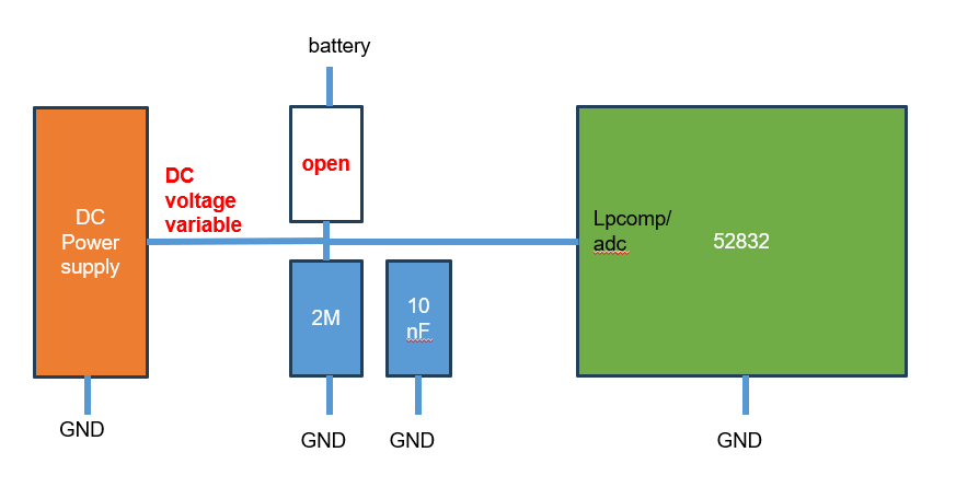
2-1) Review Symptoms

- LPCOMP: When it is lower than the reference voltage, check that it wakes up normally

- ADC: After LPCOMP wakes up, if the ADC is read and it is lower than the reference voltage, the LED should turn on, but the LED remains OFF

-> The strange thing is that after lowering the voltage below the low battery voltage and checking the wake-up by LPCOMP,

If the low voltage LED does not turn on by ADC, and the voltage is slightly increased by 0.1V, the low voltage is detected by ADC.

==============================================================================================================================================

We are producing products using the nRF52832. During production, a defect occurred where the lpcomp detection voltage was operating at a voltage lower than the design voltage.

This defect occurs in approximately 5% of devices.

This issue has occurred before, and I've asked two questions, but none have been resolved.

Please refer to the previous question below for the circuit diagram and source code.

- Question 1)   When detecting low battery voltage using LPCOMP and ADC, the detection voltage changes (occurs approximately 5%) 

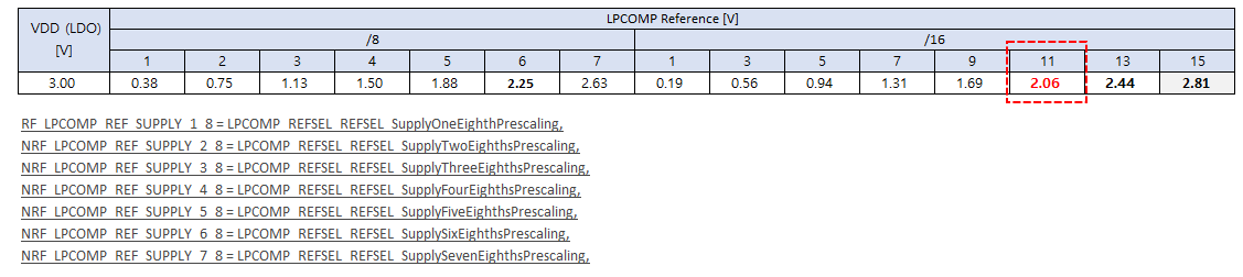
- Question 2)  The reference voltage setting of lpcom does not match the calculation 

I finally found a solution to a problem that kept occurring in small numbers during production.

Previously, if lpcomp was detected at "1)", the ADC for "2)" would be performed.

However, on the PCB where the lpcomp issue occurred, detecting lpcomp at "1)" and always performing ADC at "2)" allowed normal operation.

1) Read lpcomp.

nrf_lpcomp_task_trigger(NRF_LPCOMP_TASK_START);
nrf_lpcomp_task_trigger(NRF_LPCOMP_TASK_SAMPLE);
nrf_lpcomp_result_get_temp = nrf_lpcomp_result_get();

2) Stop lpcomp, process ADC once, and start again.

nrf_drv_lpcomp_disable();
temp_bat = BatVoltage();
nrf_drv_lpcomp_enable();

I don't understand why, after lpcomp operation, disabling lpcomp, doing ADC, and then enabling lpcomp again causes normal operation.

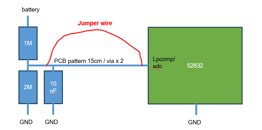
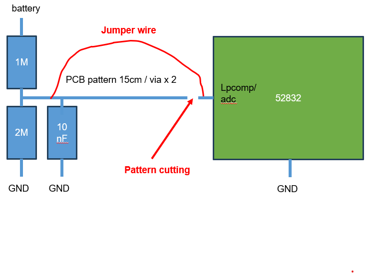
* Additionally, there are five products with identical circuitry and SW configurations, but with different PCB patterns.

However, this issue only occurs in one of the five products. The only difference is the PCB pattern.

The PCBs with the pattern differences are located at 1M and 2M, and the pattern distance between the 1nF resistor and the ADC port is approximately 15cm. (The lines indicated by the arrows in the image below.)

However, the four PCBs that are functioning normally are almost directly adjacent.

Could this be the cause?


Parents
  • Hi,

    pkr2258 said:

    I tried this implementation.

    I tested it by turning on only the LED and seeing if it would operate properly at low voltages, and I also used debugging to verify it.

    What I'm suggesting is that you decouple the LED from your debugging as it introduces other dependencies. Instead use the log module or just measure directly on a GPIO.

    pkr2258 said:

    I'm experimenting with a separate, precise external DC power source (instead of a battery).

    I switched to the ADC mentioned above, and measured the voltage across the 1M and 2M resistors when the voltage was normal and when it wasn't. The results were nearly identical.

    By any chance, are you saying that I should try to adjust the voltage by directly connecting it to the lpcom terminal?

    Yes, I'm suggesting that you circumvent the external LDO as well, connect VDD to port 1 of supply and then connect AIN to another supply and see if your code logic behaves as expected when VDD is decreased.

    pkr2258 said:
    Shall we continue the question here?

    You can continue here

    best regards

    Jared 

  • Hi

    pkr2258 said:

    I'm experimenting with a separate, precise external DC power source (instead of a battery).

    I switched to the ADC mentioned above, and measured the voltage across the 1M and 2M resistors when the voltage was normal and when it wasn't. The results were nearly identical.

    By any chance, are you saying that I should try to adjust the voltage by directly connecting it to the lpcom terminal?

    Yes, I'm suggesting that you circumvent the external LDO as well, connect VDD to port 1 of supply and then connect AIN to another supply and see if your code logic behaves as expected when VDD is decreased.

    .

    .

    * original composition

    .

    .

    .

    * test configuration

    - When configured as shown below, it operates properly at normal voltages.

    - It's not a problem with the open circuit, 1MΩ. Replacing it and measuring it again revealed it was normal.

    Looking at the results above,

    is there a problem with the input impedance of the nRF52832's lpcom?

    Damage caused by static electricity or other factors, such as careless handling.

    .

    I haven't tried swapping the chips in the nRF52832 chipset between a good and a defective one.

    I'll try it and post the results.

    .

    .

    .

    I did some additional experiments

    .

    I tried connecting jumper wires in parallel to the existing pattern.

    But the problem was not solved

    .

    .

    This time, I cut the pattern like the image below and tested it, but the problem was not solved.

    .

Reply
  • Hi

    pkr2258 said:

    I'm experimenting with a separate, precise external DC power source (instead of a battery).

    I switched to the ADC mentioned above, and measured the voltage across the 1M and 2M resistors when the voltage was normal and when it wasn't. The results were nearly identical.

    By any chance, are you saying that I should try to adjust the voltage by directly connecting it to the lpcom terminal?

    Yes, I'm suggesting that you circumvent the external LDO as well, connect VDD to port 1 of supply and then connect AIN to another supply and see if your code logic behaves as expected when VDD is decreased.

    .

    .

    * original composition

    .

    .

    .

    * test configuration

    - When configured as shown below, it operates properly at normal voltages.

    - It's not a problem with the open circuit, 1MΩ. Replacing it and measuring it again revealed it was normal.

    Looking at the results above,

    is there a problem with the input impedance of the nRF52832's lpcom?

    Damage caused by static electricity or other factors, such as careless handling.

    .

    I haven't tried swapping the chips in the nRF52832 chipset between a good and a defective one.

    I'll try it and post the results.

    .

    .

    .

    I did some additional experiments

    .

    I tried connecting jumper wires in parallel to the existing pattern.

    But the problem was not solved

    .

    .

    This time, I cut the pattern like the image below and tested it, but the problem was not solved.

    .

Children
No Data
Related