Hello~
I am developing nrf52840 with zephyr ncs tool chain v2.7.0 and SDK v2.6.1.
Our hadware is very simple, just a power IC, a nrf52840 and a G-sensor.
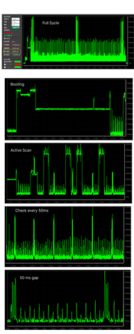
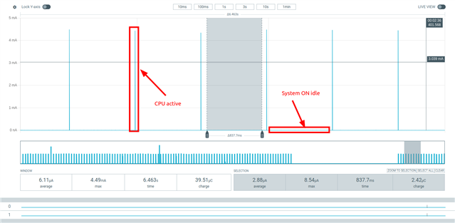
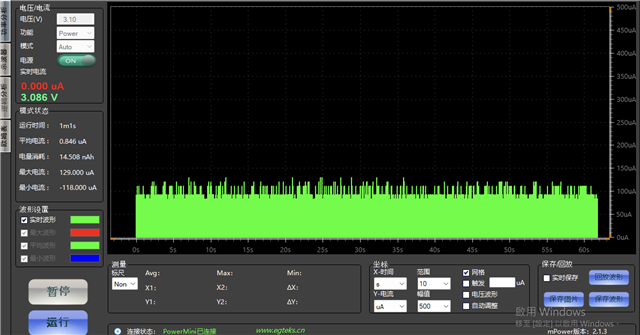
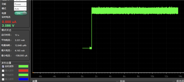
Our pre-production PCB average current is 600uA when normal operating. We want to minimize it to around 120uA (This is the estimate current value we get from here: Online Power Profiler for Bluetooth LE )
When normal operation, without scan, with advertising and sleep 100 ms in main loop. And we turned on ADC, I2C also.
And when normal operation, G-sensor is off.
We turn on DCDC also.
This is our Device tree, we had turned off all unused function blocks.
/ {
    zephyr,user {
        io-channels = <&adc 0>;
    };

    // redefine button pins
    // Left :   buttonL
    // Right :  buttonR
    // Up:      buttonU
    // Down :   buttonD
    // PWR  :   buttonP
    buttons {
        compatible = "gpio-keys";
        debounce-interval-ms = <200>;
        buttonL: button_0 {
            gpios = <&gpio0 26 (GPIO_PULL_UP | GPIO_ACTIVE_LOW)>;
            label = "Left button switch 1";
            zephyr,code = <INPUT_KEY_0>;
        };

        buttonR: button_1 {
            gpios = <&gpio0 27 (GPIO_PULL_UP | GPIO_ACTIVE_LOW)>;
            label = "Right button switch 2";
            zephyr,code = <INPUT_KEY_1>;
        };

        buttonU: button_2 {
            gpios = <&gpio0 6 (GPIO_PULL_UP | GPIO_ACTIVE_LOW)>;
            label = "Up button switch 3";
            zephyr,code = <INPUT_KEY_2>;
        };

        buttonP: button_3 {        // the middle one
            gpios = <&gpio0 7 (GPIO_PULL_UP | GPIO_ACTIVE_LOW)>;
            label = "Down button switch 4";
            zephyr,code = <INPUT_KEY_3>;
        };

        buttonB: button_4 {        // the bottom one
            gpios = <&gpio0 5 (GPIO_PULL_UP | GPIO_ACTIVE_LOW)>;
            label = "Power button switch 5";
            zephyr,code = <INPUT_KEY_5>;
        };

    };

    leds {
		compatible = "gpio-leds";
		led0: led_0 {
			gpios = <&gpio1 4 GPIO_ACTIVE_LOW>;
			label = "Red LED 0";
		};
		led1: led_1 {
			gpios = <&gpio1 7 GPIO_ACTIVE_LOW>;
			label = "Green LED 1";
		};
		led2: led_2 {
			gpios = <&gpio1 6 GPIO_ACTIVE_LOW>;
			label = "Blue LED 2";
		};
	};

    aliases {
        btn0 = &buttonL;
        btn1 = &buttonR;
        btn2 = &buttonU;
        btn3 = &buttonP;
		btn4 = &buttonB;
    };

    gpio-inputs
    {
        compatible = "gpio-keys";
        gsensor_int: gsensor_int {
            gpios = <&gpio0 11 (GPIO_ACTIVE_HIGH)>;
            label = "g-sensor interrupt";
            zephyr,code = <INPUT_KEY_6>;
        };
    };

    gpio-outputs
    {
        compatible = "gpio-leds";
        adc_en: adc_en {
            gpios = <&gpio0 3 GPIO_ACTIVE_HIGH>;
            label = "ADC enable";
        };
    };
};

&adc {
       #address-cells = <1>;
       #size-cells = <0>;
       status= "okay";
       channel@0 {
           reg= <0>;

           zephyr,gain = "ADC_GAIN_1_6";
           zephyr,reference = "ADC_REF_INTERNAL";
           zephyr,acquisition-time = <ADC_ACQ_TIME(ADC_ACQ_TIME_MICROSECONDS, 10)>; //<ADC_ACQ_TIME_DEFAULT> : 10us
           zephyr,input-positive = <NRF_SAADC_AIN2>; // P0.04
           zephyr,resolution = <12>;
           zephyr,oversampling = <8>;
       };
};


&i2c0 {
	compatible = "nordic,nrf-twim";
	status = "okay";
	clock-frequency = <100000>;
    pinctrl-0 = <&i2c0_default>;
	pinctrl-1 = <&i2c0_sleep>;
    zephyr,concat-buf-size = <64>;
    zephyr,flash-buf-max-size = <64>;
	/*Gsensor:Gsensor@50 {
        compatible = "i2c-device";
		label = "i2c Gsensor addr 0x50";
		reg = <0x50>;
	};*/
};

&pinctrl {
    i2c0_default: i2c0_default {
        group1 {
            psels = <NRF_PSEL(TWIM_SDA, 0, 12)>,
                <NRF_PSEL(TWIM_SCL, 0, 13)>;
        };
    };

    i2c0_sleep: i2c0_sleep {
		group1 {
			psels = <NRF_PSEL(TWIM_SDA, 0, 12)>,
				<NRF_PSEL(TWIM_SCL, 0, 13)>;
			low-power-enable;
		};
	};

    // reserve form mp debug
    uart0_default: uart0_default {
		group1 {
			psels = <NRF_PSEL(UART_TX, 0, 29)>,
				<NRF_PSEL(UART_RTS, 0, 8)>;
		};
		group2 {
			psels = <NRF_PSEL(UART_RX, 0, 30)>,
				<NRF_PSEL(UART_CTS, 0, 7)>;
			bias-pull-up;
		};
	};

	uart0_sleep: uart0_sleep {
		group1 {
			psels = <NRF_PSEL(UART_TX, 0, 29)>,
				<NRF_PSEL(UART_RX, 0, 30)>,
				<NRF_PSEL(UART_RTS, 0, 8)>,
				<NRF_PSEL(UART_CTS, 0, 7)>;
			low-power-enable;
		};
	};

};

//uart0 confict with button3,4
&uart0 {
    status="disabled";
};

&uart1 {
    status="disabled";
};

&pwm0 {
    status="disabled";
};

&i2c1 {
    status="disabled";
};

&spi0 {
    status="disabled";
};

&spi1 {
    status="disabled";
};

&qspi {
    status="disabled";
};

&spi3 {
    status="disabled";
};

&ieee802154 {
    status="disabled";
};

&usbd {
    status="disabled";
};


&power {
    status = "okay";
};

&clock {
    status = "okay";
};

&acl {
    status = "disabled";
};

&cryptocell {
    status = "okay";
};

&temp {
    status = "disabled";
};

&nfct {
    status = "disabled";
};

&wdt {
    status = "disabled";
};
This is power management settings in our project:
CONFIG_PM_DEVICE=y
CONFIG_PM_DEVICE_RUNTIME=y
CONFIG_POWEROFF=y
CONFIG_PM_CPU_OPS=y
CONFIG_BOARD_ENABLE_DCDC=y
Do you have any ideas on "how to minimize operating current to 120 uA " ?