Good evening,
I have been working for a while on a project that requires the maximum possible speed from both app core and SPIM4 peripheral. To do so, I set the app core clock speed to 128MHz executing these lines as first operation in main function:
printk("CPU clock during booting: %u Hz\n", SystemCoreClock);
printk("NRF_CLOCK_S.HFCLKCTRL:%d\n",NRF_CLOCK_S->HFCLKCTRL);
printk("Switching application core from 64 MHz and 128 MHz. \n");
*(volatile uint32_t *)0x5084450C= 0x4040;
*(volatile uint32_t *)0x50026548 = 0x40;
*(volatile uint32_t *)0x50081EE4 = 0x4D;
NRF_CLOCK_S->HFCLKCTRL = 0;
nrfx_clock_divider_set(NRF_CLOCK_DOMAIN_HFCLK, NRF_CLOCK_HFCLK_DIV_1);
printk("NRF_CLOCK_S.HFCLKCTRL:%d\n", NRF_CLOCK_S->HFCLKCTRL);
printk("Check freq status running:%d\n", NRF_CLOCK_S->HFCLKSTAT);
for what concerns the SPIM4 configuration, in the overlay file I have:
for what concerns the SPIM4 configuration, in the overlay file I have:
&pinctrl {
spi4_default: spi4_default {
group1 {
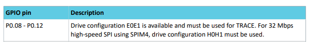
nordic,drive-mode = <NRF_DRIVE_H0H1>;
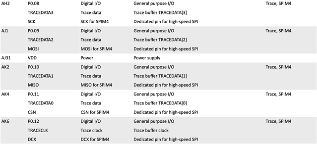
psels = <NRF_PSEL(SPIM_MOSI, 0, 9)>,
<NRF_PSEL(SPIM_SCK, 0, 8)>,
<NRF_PSEL(SPIM_MISO, 0, 12)>;
};
};
spi4_sleep: spi4_sleep {
group1 {
nordic,drive-mode = <NRF_DRIVE_H0H1>;
psels = <NRF_PSEL(SPIM_MOSI, 0, 9)>,
<NRF_PSEL(SPIM_SCK, 0, 8)>,
<NRF_PSEL(SPIM_MISO, 0, 12)>;
low-power-enable;
};
};
&spi4 {
cs-gpios = <&gpio0 11 GPIO_ACTIVE_LOW>;
compatible = "nordic,nrf-spim";
max-frequency = <DT_FREQ_M(16)>;
#address-cells = <1>;
#size-cells = <0>;
rx-delay-supported;
rx-delay = <0>;
status = "okay";
pinctrl-0 = <&spi4_default>;
pinctrl-1 = <&spi4_sleep>;
pinctrl-names = "default", "sleep";
};
NOTE: at the moment max-frequency is set to 16MHz and MISO pin is associated to P0.12 since it was the only way I found to make this peripheral work.
in main function, instead I execute this function after setting the app core clock freq. to 128MHz:
in main function, instead I execute this function after setting the app core clock freq. to 128MHz:
bool spim_initialization(void)
{
nrfx_spim_config_t spim_config = NRFX_SPIM_DEFAULT_CONFIG(SCK_PIN,
MOSI_PIN,
MISO_PIN,
CS1_PIN);
spim_config.frequency = NRFX_MHZ_TO_HZ(16);
spim_config.miso_pull = NRF_GPIO_PIN_NOPULL;
NRFX_COND_CODE_1(NRFX_SPIM_EXTENDED_ENABLED, (spim_config.use_hw_ss = true; spim_config.ss_duration = 0x01;), ()); //prova con 0x00
nrfx_err_t status = nrfx_spim_init(&spim_inst, &spim_config, NULL, NULL);
if (status != NRFX_SUCCESS)
{
printk("SPI initialization failed with error code: %d\n", status);
return 0;
}
else
{
return 1;
}
}
I read some tickets that mentioned about the UARTE pin control configuration on net core, but I do not know how I could fix this. So my questions are:
- how to make SPIM4 work at 32MHz?
- how to make SPIM4 work at 32MHz?
- how to make MISO pin associated with P0.10 work? -- in this sense, how could I integrate e.g. another overlay file for the cpunet core that changes uarte pin control configuration to my project? ( I work on VS code on MacOS).
- should I execute *(volatile uint32_t *)0x5000ac04 = 1; ? if yes, at which point of my main function?
NOTE 2: SPIM4 configured as above seems to work at 16MHz, configuring P0.12 as MISO pin.
Thank you,
Sara L.