nrf5340dk - sdk v2.6.1 - SPIM4 designed pin P0.10 & 32MHz speed not working

Good evening,

I have been working for a while on a project that requires the maximum possible speed from both app core and SPIM4 peripheral. To do so, I set the app core clock speed to 128MHz executing these lines as first operation in main function:

printk("CPU clock during booting: %u Hz\n", SystemCoreClock);
printk("NRF_CLOCK_S.HFCLKCTRL:%d\n",NRF_CLOCK_S->HFCLKCTRL);
printk("Switching application core from 64 MHz and 128 MHz. \n");
*(volatile uint32_t *)0x5084450C= 0x4040;
*(volatile uint32_t *)0x50026548 = 0x40;
*(volatile uint32_t *)0x50081EE4 = 0x4D;
NRF_CLOCK_S->HFCLKCTRL = 0;
nrfx_clock_divider_set(NRF_CLOCK_DOMAIN_HFCLK, NRF_CLOCK_HFCLK_DIV_1);
printk("NRF_CLOCK_S.HFCLKCTRL:%d\n", NRF_CLOCK_S->HFCLKCTRL);
printk("Check freq status running:%d\n", NRF_CLOCK_S->HFCLKSTAT);

for what concerns the SPIM4 configuration, in the overlay file I have:

&pinctrl {
spi4_default: spi4_default {
group1 {
nordic,drive-mode = <NRF_DRIVE_H0H1>;
psels = <NRF_PSEL(SPIM_MOSI, 0, 9)>,
<NRF_PSEL(SPIM_SCK, 0, 8)>,
<NRF_PSEL(SPIM_MISO, 0, 12)>;
};
};
spi4_sleep: spi4_sleep {
group1 {
nordic,drive-mode = <NRF_DRIVE_H0H1>;
psels = <NRF_PSEL(SPIM_MOSI, 0, 9)>,
<NRF_PSEL(SPIM_SCK, 0, 8)>,
<NRF_PSEL(SPIM_MISO, 0, 12)>;
low-power-enable;
};
};

&spi4 {
cs-gpios = <&gpio0 11 GPIO_ACTIVE_LOW>;
compatible = "nordic,nrf-spim";
max-frequency = <DT_FREQ_M(16)>;
#address-cells = <1>;
#size-cells = <0>;
rx-delay-supported;
rx-delay = <0>;
status = "okay";
pinctrl-0 = <&spi4_default>;
pinctrl-1 = <&spi4_sleep>;
pinctrl-names = "default", "sleep";
};
NOTE: at the moment max-frequency is set to 16MHz and MISO pin is associated to P0.12 since it was the only way I found to make this peripheral work. 

in main function, instead I execute this function after setting the app core clock freq. to 128MHz:


bool spim_initialization(void)
{
nrfx_spim_config_t spim_config = NRFX_SPIM_DEFAULT_CONFIG(SCK_PIN,
MOSI_PIN,
MISO_PIN,
CS1_PIN);
spim_config.frequency = NRFX_MHZ_TO_HZ(16);
spim_config.miso_pull = NRF_GPIO_PIN_NOPULL;
NRFX_COND_CODE_1(NRFX_SPIM_EXTENDED_ENABLED, (spim_config.use_hw_ss = true; spim_config.ss_duration = 0x01;), ()); //prova con 0x00

nrfx_err_t status = nrfx_spim_init(&spim_inst, &spim_config, NULL, NULL);
if (status != NRFX_SUCCESS)
{
printk("SPI initialization failed with error code: %d\n", status);
return 0;
}
else
{
return 1;
}
}
I read some tickets that mentioned about the UARTE pin control configuration on net core, but I do not know how I could fix this. So my questions are:

- how to make SPIM4 work at 32MHz?
- how to make MISO pin associated with P0.10 work? -- in this sense, how could I integrate e.g. another overlay file for the cpunet core that changes uarte pin control configuration to my project? ( I work on VS code on MacOS).  
- should I execute *(volatile uint32_t *)0x5000ac04 = 1; ? if yes, at which point of my main function?
NOTE 2: SPIM4 configured as above seems to work at 16MHz, configuring P0.12 as MISO pin.
Thank you, 
Sara L.
Parents
  • Hello,

    If have problems with achieving specific frequency, connect a oscilloscope or logic analyzer (with analog input) and look at the signals, I suspect it may be combination of drive level of the pins and capacitance on the pins. So possibly enable high drive on the pins in question, for instance it says in the datasheet:

    Hope that helps,
    Kenneth

  • Hi Kenneth, 

    thank you for your help.

    Actually, I've already enabled high drive on pins dedicated to spi4, please check the first lines of overlay file I wrote in the previous message that I re-write here: 

    &pinctrl {
    spi4_default: spi4_default {
    group1 {
    nordic,drive-mode = <NRF_DRIVE_H0H1>;
    ...
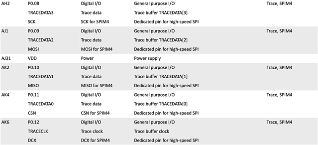
    also, theoretically SPIM4 should be configured so that P0.11 corresponds to CS, P0.08 to SCLK, P0.09 to MOSI and P.10 to MISO:


    since P0.10 gives no output when configured as MISO, I chose P0.12 as MISO itself for my SPIM4 configuration. 

    I would like to understand how to fix this problem first (having P0.10 as MISO SPIM4 at 16M speed), then how to configure SPIM4 at 32M speed.
    thank you, 
    Sara
  • Sara Lo Vecchio said:
    since P0.10 gives no output when configured as MISO, I chose P0.12 as MISO itself for my SPIM4 configuration. 

    Not sure I understand. The MISO pin will not be driven by the nRF5340, its an master in slave out, which means it a input pin of the nRF5340.

    Kenneth

  • Sorry, to be clearer, let's say that configuring P0.10 as MISO of SPIM4 the received data read from rx buffer is all zeros (also checking from P0.10 on oscilloscope). Configuring P0.12 as MISO instead, allows us to receive and read the expected output from slave.

Reply Children
  • Presuming P0.10 is not used by any other peripheral in devicetree, then I don't see any reason why this should not work.

    Kenneth

  • here in the following lines you can find my nrf5340dk_nrf5340_cpuapp.overlay complete file. I can guarantee that MISO signal is not properly received from P0.10 with the following configuration.

    &pinctrl {
    spi4_default: spi4_default {
    group1 {
    nordic,drive-mode = <NRF_DRIVE_H0H1>;
    psels = <NRF_PSEL(SPIM_MOSI, 0, 9)>,
    <NRF_PSEL(SPIM_SCK, 0, 8)>,
    <NRF_PSEL(SPIM_MISO, 0, 10)>;
    };
    };
    spi4_sleep: spi4_sleep {
    group1 {
    nordic,drive-mode = <NRF_DRIVE_H0H1>;
    psels = <NRF_PSEL(SPIM_MOSI, 0, 9)>,
    <NRF_PSEL(SPIM_SCK, 0, 8)>,
    <NRF_PSEL(SPIM_MISO, 0, 10)>;
    low-power-enable;
    };
    };
    spi1_default: spi1_default {
    group1 {
    psels = <NRF_PSEL(SPIM_SCK, 0, 6)>,
    <NRF_PSEL(SPIM_MOSI, 0, 5)>,
    <NRF_PSEL(SPIM_MISO, 0, 26)>;
    };
    };
    spi1_sleep: spi1_sleep {
    group1 {
    psels = <NRF_PSEL(SPIM_SCK, 0, 6)>,
    <NRF_PSEL(SPIM_MOSI, 0, 5)>,
    <NRF_PSEL(SPIM_MISO, 0, 26)>;
    low-power-enable;
    };
    };
    };

    &spi4 {
    cs-gpios = <&gpio0 11 GPIO_ACTIVE_LOW>;
    compatible = "nordic,nrf-spim";
    max-frequency = <DT_FREQ_M(16)>;
    #address-cells = <1>;
    #size-cells = <0>;
    rx-delay-supported;
    rx-delay = <0>;
    status = "okay";
    pinctrl-0 = <&spi4_default>;
    pinctrl-1 = <&spi4_sleep>;
    pinctrl-names = "default", "sleep";
    };

    &spi1 {
    compatible = "nordic,nrf-spim";
    status = "okay";
    pinctrl-0 = <&spi1_default>;
    pinctrl-1 = <&spi1_sleep>;
    interrupts = <9 NRF_DEFAULT_IRQ_PRIORITY>;
    max-frequency = <DT_FREQ_M(8)>;
    pinctrl-names = "default", "sleep";
    cs-gpios = <&gpio0 25 GPIO_ACTIVE_LOW>;
    sdhc0: sdhc@0 {
    compatible = "zephyr,sdhc-spi-slot";
    reg = <0>;
    status = "okay";
    spi-max-frequency = <25000000>;
    mmc {
    compatible = "zephyr,sdmmc-disk";
    status = "okay";
    };
    };
    };

    &button2 {
    gpios = <&gpio0 7 0>;
    status = "disabled";
    };

    &button3 {
    gpios = <&gpio0 27 0>;
    status = "disabled";
    };

    &timer0 {
    status = "okay";
    };
    &timer1 {
    status ="okay";
    };

    &timer2 {
    status ="okay";
    };

    / {
    chosen {
    zephyr,shell-uart = &uart0;
    };
    aliases {
    led0 = &led0;
    sw0 = &button0;
    };
    };

    &i2c0 { status = "disabled";};
    &spi0 { status = "disabled";};
    &i2c1 { status = "disabled";};
    &adc { status = "disabled";};
    &qspi { status = "disabled";};
    &uart1 { status = "disabled";};

    &gpio_fwd {
    uart {
    gpios = <&gpio0 0 0>, <&gpio0 1 0>, <&gpio1 1 0>, <&gpio1 0 0>;
    };
    status = "disabled";
    };


  • I thought that maybe there is some other peripherals that is already associated with P0.10 through some default configuration in the NET core? 

  • Correct me if I am wrong, but maybe P0.10 could be configured on NET core as uart0 UART_CTS pin (saw it on nrf5340dk_nrf5340_cpunet.pincntrl.dtsi file in sdk v2.6.1>zephyr>boards>arm>nrf5340dk_nrf5340 folder). 

    considering that I have worked on APP core only so far, how could I modify this configuration?

    - i enabled CONFIG_BT=in my prj.conf file;

    - should I put gpio_fwd status as enabled and perhaps change part gpio pins?

    - should I add another .overlay file for the NET core and add it as Extra devicetree overlay in my build configuration?

    could you propose any other solution for me?

    thank you

  • If you enable log/serial from the netcore it will use uart pins yes, however the netcore should not be able to control pins that the appcore don't add to the overlay/dts file for the gpio_fwd: nrf-gpio-forwarder node. So maybe take a look at the zephyr.dts file in the build folder for the appcore and check which pins that are given control to the netcore.

    Kenneth

Related