Error setting sampling frequency on lsm6dso - nrf52833

Hi all,

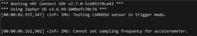
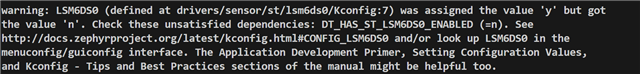
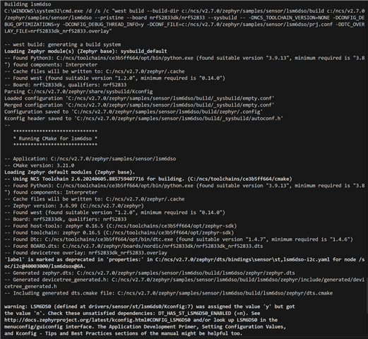
I am running the lsm6dso zephyr sample on my nrf52833 dev kit. I am unable to set the sampling frequency. I get this error after flashing:

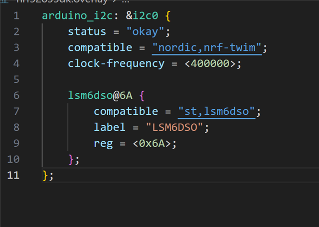
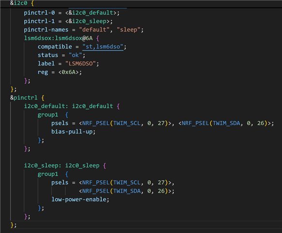
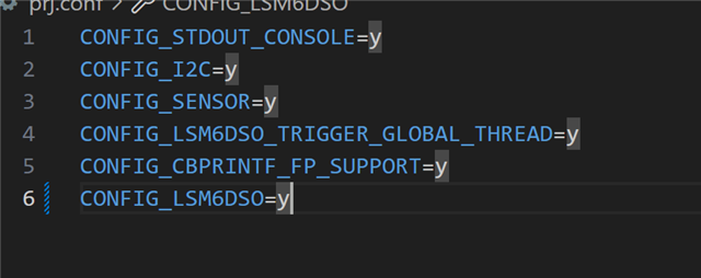
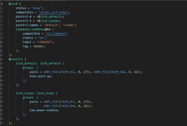
This is my overlay file:

My SDK version is 2.7 and I am on Zephyr 3.6.99

My debugger suggests that the issue could be from this case failing in i2c_nrfx_twim.c

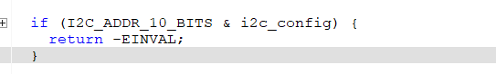
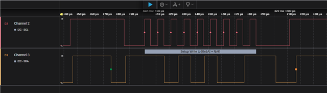
However, the IMU address is listed at 7 bits long in the datasheet.

Does anyone have any suggestions?

Parents Reply Children
  • The sample is unchanged, just added your file to the folder-structure.


    Kind regards,

    Håkon

  • I redid my build, and the config error went away. Thanks for that

    However I am still unable to communicate with my sensor.

    This is my scoping of the SDA and SCL pins. The pins sit at high, then when I restart the board thats when both the pins go low, then they sit at high continuously. 

    I am using the same sample https://github.com/zephyrproject-rtos/zephyr/tree/main/samples/sensor/lsm6dso I just changed one line in main due to getting a "device not ready" error:

    This is my proj.conf file:

    And the overlay file is the same one I sent a couple days ago

    This is the sensor board I have

    https://www.st.com/en/evaluation-tools/steval-mki217v1.html

    Is there any possible configurations I could be missing to enable i2c communication? I have verified the connection of SDA/SCL/VDD and GND pins.

    Thanks for your time

  • Hi,


    Please note that zephyr supports lsm6dso, and not lsm6dsox directly. I do not know the exact difference between the two sensors, but they seem to have a similar i2c address atleast.


    If you zoom into the rising edge of your saleae logic trace at approx. +0.5 sec, you should see some i2c communication. Please share this, and check if the sensor ACKs.


    ReginaA101 said:

    This is the sensor board I have

    https://www.st.com/en/evaluation-tools/steval-mki217v1.html

    Is there any possible configurations I could be missing to enable i2c communication? I have verified the connection of SDA/SCL/VDD and GND pins.

    There is two sensors on this board, you will have to make sure that the board itself is not modified, as the default is to have both sensors connected over the common i2c lines.

    ReginaA101 said:

    I am using the same sample https://github.com/zephyrproject-rtos/zephyr/tree/main/samples/sensor/lsm6dso I just changed one line in main due to getting a "device not ready" error:

    It seems like you have changed this line:

    https://github.com/zephyrproject-rtos/zephyr/blob/main/samples/sensor/lsm6dso/src/main.c#L111C53-L111C63


    I would strongly recommend that you keep this "as-is", ie. revert your change, as this line is crucial in terms of initializing and using the lsm6dso sensor driver.


    Kind regards,

    Håkon


  • Thanks for your suggestions 

    I have reverted the change

    I am still getting a device not ready error.

    I zoomed into the section you told me and I am getting an initialization. Seems that the first 7 bits are 6A which was the i2c address I believe.

    It doesnt seem like I am getting any ACK though

  • Hi,


    Your sensor does not ACK (ie. NAK), as the LSBit in the transaction is high, indicating that there is a problem on the sensor side.


    You should go over your physical connection and see if there's anything that isn't properly connected (VDD, VDDIO, GND, SDA and SCL).


    Kind regards,

    Håkon