NRF Power Profiler II not working in AMP mode

Hi guys,

I'm a bit frustrated with the NRF Power Profiler II. I'm working on a low power project with the NRF52832 with a custom PCB and I decided to buy this power profiler to ease the debug.

In voltage mode the device works perfectly. Using a 10K resistor between the Vout and GND gives the 400uA if the voltage is set to 4V.

However, in AMP mode nothing makes sense. I've a battery with around the same voltage with positive cable connected to Vin and a resistor connected to Vout which then connects to the negative cable of the battery. The reading in the tool shows 14uA. Using the multimeter I got a voltage across the resistor around 3.6V which also does not make much sense. It seems the tool is drawing some current itself?

Is this a defective product or it's software related?

Best regards,

Fernando Fontes

Parents
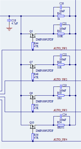
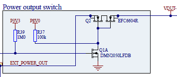
  • My (unofficial) drawing might help; note the resistor (labelled DUT) must connect to the PPK-II Gnd and not just the battery negative. The PPK-II is not a 2-wire current meter but a 3-terminal voltage monitor which reads the voltage across the internal series resistor RC where Resistor Rc used for current sense is 1k0 in parallel with none or more of 110R, 11R0, 1R0 and 0R051.

    // Resistor Rc for current sense is 1k0 in parallel with one or more of 110R, 11R0, 1R0 and 0R051
    //
    //              <- +ve Supply to DUT From VOUT                               External Battery +ve To VIN
    //             +------------------------------+                             +-----------------------+
    //             |                              |                             |                       |
    //             |              +---------+     |                             |     +---------+       |
    //             |              |     GND |     | VOUT                   VIN  |     | GND -ve |       |
    //   +=========O=========+    |    +====O=====O=============================O=====O====+    |       | Battery
    //   |        Vdd (+)    |    |    |    |     #----+                        |     |    |    |       | + 3 volts
    //   |                   |    |    |    |     |    |Rc        AMPERE \      |     |    |    |     +-O-+
    //   |                   |    |    |    |     |   +++                 \     |     |    |    |     |   |
    //   |                   |    |    |    |     |   | |   +-----------O  O----#     |    |    |     |   |
    //   | Device Under Test |    |    |    |     |   | |   |                   |     |    |    |     |   |
    //   |       DUT         |    |    |    | 120k|   | |   |                   |120k |    |    |     |   |
    //   |                   |    |    |    |    +++  +++   |   \  SOURCE      +++    |    |    |     |   |
    //   |                   |    |    |    |    | |   |    |    \             | |    |    |    |     +-O-+
    //   |                   |    |    |    |    | |   +----#--O  O-- PPK LDO  | |    |    |    |       | Gnd (-)
    //   |                   |    |    |    |    | |                           | |    |    |    +-------+
    //   |                   |    |    |    |    +++                           +++    |    |
    //   |                   |    |    |    |     |                             |     |    |
    //   |                   |    |    |    |     #-- VDUT                VIN --#     |    |
    //   |                   |    |    |    |     |  Sense                Sense |     |    |
    //   |                   |    |    |    |    +++                           +++    |    |
    //   |                   |    |    |    |    | |                           | |    |    |
    //   |                   |    |    |    |    | |                           | |    |    |
    //   |                   |    |    |    |    | |                           | |    |    |
    //   |                   |    |    |    |    +++                           +++    |    |
    //   |                   |    |    |    |     | 30k                     30k |     |    |
    //   |                   |    |    |    +--#--+                             +--#--+    |
    //   |                   |    |    |       |                                   |       |
    //   |                   |    |    |     =====      <<== Common Gnd ==>>     =====     |
    //   |                   |    |    |      ===           (Common -ve)          ===      |
    //   |        Gnd (-)    |    |    |       =                                   =       |
    //   +=========O=========+    |    +===================================================+
    //             |              |     PPK-II
    //             +--------------+
    

Reply
  • My (unofficial) drawing might help; note the resistor (labelled DUT) must connect to the PPK-II Gnd and not just the battery negative. The PPK-II is not a 2-wire current meter but a 3-terminal voltage monitor which reads the voltage across the internal series resistor RC where Resistor Rc used for current sense is 1k0 in parallel with none or more of 110R, 11R0, 1R0 and 0R051.

    // Resistor Rc for current sense is 1k0 in parallel with one or more of 110R, 11R0, 1R0 and 0R051
    //
    //              <- +ve Supply to DUT From VOUT                               External Battery +ve To VIN
    //             +------------------------------+                             +-----------------------+
    //             |                              |                             |                       |
    //             |              +---------+     |                             |     +---------+       |
    //             |              |     GND |     | VOUT                   VIN  |     | GND -ve |       |
    //   +=========O=========+    |    +====O=====O=============================O=====O====+    |       | Battery
    //   |        Vdd (+)    |    |    |    |     #----+                        |     |    |    |       | + 3 volts
    //   |                   |    |    |    |     |    |Rc        AMPERE \      |     |    |    |     +-O-+
    //   |                   |    |    |    |     |   +++                 \     |     |    |    |     |   |
    //   |                   |    |    |    |     |   | |   +-----------O  O----#     |    |    |     |   |
    //   | Device Under Test |    |    |    |     |   | |   |                   |     |    |    |     |   |
    //   |       DUT         |    |    |    | 120k|   | |   |                   |120k |    |    |     |   |
    //   |                   |    |    |    |    +++  +++   |   \  SOURCE      +++    |    |    |     |   |
    //   |                   |    |    |    |    | |   |    |    \             | |    |    |    |     +-O-+
    //   |                   |    |    |    |    | |   +----#--O  O-- PPK LDO  | |    |    |    |       | Gnd (-)
    //   |                   |    |    |    |    | |                           | |    |    |    +-------+
    //   |                   |    |    |    |    +++                           +++    |    |
    //   |                   |    |    |    |     |                             |     |    |
    //   |                   |    |    |    |     #-- VDUT                VIN --#     |    |
    //   |                   |    |    |    |     |  Sense                Sense |     |    |
    //   |                   |    |    |    |    +++                           +++    |    |
    //   |                   |    |    |    |    | |                           | |    |    |
    //   |                   |    |    |    |    | |                           | |    |    |
    //   |                   |    |    |    |    | |                           | |    |    |
    //   |                   |    |    |    |    +++                           +++    |    |
    //   |                   |    |    |    |     | 30k                     30k |     |    |
    //   |                   |    |    |    +--#--+                             +--#--+    |
    //   |                   |    |    |       |                                   |       |
    //   |                   |    |    |     =====      <<== Common Gnd ==>>     =====     |
    //   |                   |    |    |      ===           (Common -ve)          ===      |
    //   |        Gnd (-)    |    |    |       =                                   =       |
    //   +=========O=========+    |    +===================================================+
    //             |              |     PPK-II
    //             +--------------+
    

Children
  • Thanks.

    One more question, I've been using the tool quite a lot and on this last project where I've a inboard dc-dc boost, the tool was reading averages currents of 0.6A with peaks of 1.5A.

    The power profiler is now reading an average current of 0.42uA without any load. Does this means that the power profiler is broken? I was using source mode with 5000mV... I thought that there was some protections to avoid this... 

    Is it possible to fix it? What components should I be looking for replacing?

    Best regards,

    Fernando Fontes

  • There is no physical protection that I see. Max continuous current in Ampere Mode is 1A, and in Source Mode only 600mA; this would imply the sense resistors and FETs are rated to at least 1A. Maybe test the resistance of the 0.051Ohm (0r051) resistor R54 and that Q3 and Q10 still work. The schematics include component locations.

    Also note "If the PPK2 is operating in Source Meter mode and the DUT can draw more than 400 mA, an extra external USB power supply that can deliver 1 A or more is recommended" which may also be an issue.


Related