Issue related to running unicast server application on custom board.

Hi Nordic Team and Other,

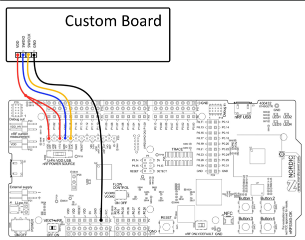
We are evaluating an audio product using a NRF5340 Audio Dk (Custom Board) and using nrf5340 DK for flashing the custom board using the setup as mentioned below.

We are using v2.9.0 and referencing the unicast server application for testing purpose.

We are using following setup to program our custom board.

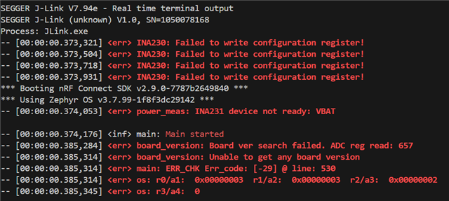
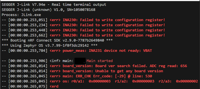
Currently, we are utilizing RTT for console messages instead of the serial port.

We are encountering issues and receiving error messages.

Please find attached the prj.conf file for the nRF audio application we are using.

2133.prj.conf

Could you kindly review the configuration and assist us in programming the custom board(this is based on the NRF5340 Audio DK)?

Thanks for your support.

Parents
  • Hi,

    Your connections mostly follow programming board with custom connections guide. You could try to replace your connection to VDD (nRF) with one to VDD (nrf') as shown in the linked document. In addition, you can look at this discussion.

    Best regards,
    Dejan

  • Hi Dejan,

    Thank you for your response.

    I changed the connection to VDD (nrf'), but I am still encountering the same error.

    I also tried flashing a different sample application (the Eddystone application) and was able to flash it successfully, with the correct output appearing on the RTT terminal.

    However, for the audio application, I am flashing both the Network MCU (ipc_radio) and the Application MCU (nrf5340_audio). Could there be a step that I am missing?

  • Hi,

    Could you please refer us to the document and section where the ADC details are mentioned for getting the board version? 

        board_id: board_id {
            compatible = "voltage-divider";
            io-channels = <&adc 0>;
            output-ohms = <20000>;
            full-ohms = <47000>;
            power-gpios = <&gpio0 24 GPIO_ACTIVE_HIGH>;
        };
    In our case, we are getting an ADC value of 656, which is way beyond the tolerance value. It seems we have an incorrect ADC configuration.
    Also, please let us know the section where we can find details on the following configuration:
    arduino_i2c: &i2c1 {
        compatible = "nordic,nrf-twim";
        status = "okay";
        pinctrl-0 = <&i2c1_default>;
        pinctrl-1 = <&i2c1_sleep>;
        pinctrl-names = "default", "sleep";

        vbat_sensor: ina231@44 {
            compatible = "ti,ina230";
            reg = <0x44>;
            adc-mode = "Bus and shunt voltage continuous";
            vbus-conversion-time-us = <4156>;
            vshunt-conversion-time-us = <4156>;
            avg-count = <1024>;
            current-lsb-microamps = <1>;
            rshunt-micro-ohms = <510000>;
        };

        vdd1_codec_sensor: ina231@45 {
            compatible = "ti,ina230";
            reg = <0x45>;
            adc-mode = "Bus and shunt voltage continuous";
            vbus-conversion-time-us = <4156>;
            vshunt-conversion-time-us = <4156>;
            avg-count = <1024>;
            current-lsb-microamps = <1>;
            rshunt-micro-ohms = <2200000>;
        };

        vdd2_codec_sensor: ina231@41 {
            compatible = "ti,ina230";
            reg = <0x41>;
            adc-mode = "Bus and shunt voltage continuous";
            vbus-conversion-time-us = <4156>;
            vshunt-conversion-time-us = <4156>;
            avg-count = <1024>;
            current-lsb-microamps = <1>;
            rshunt-micro-ohms = <2200000>;
        };

        vdd2_nrf_sensor: ina231@40 {
            compatible = "ti,ina230";
            reg = <0x40>;
            adc-mode = "Bus and shunt voltage continuous";
            vbus-conversion-time-us = <4156>;
            vshunt-conversion-time-us = <4156>;
            avg-count = <1024>;
            current-lsb-microamps = <1>;
            rshunt-micro-ohms = <1000000>;
        };
    };
  • Hi,

    embdev61 said:

    Could you please refer us to the document and section where the ADC details are mentioned for getting the board version? 

        board_id: board_id {
            compatible = "voltage-divider";
            io-channels = <&adc 0>;
            output-ohms = <20000>;
            full-ohms = <47000>;
            power-gpios = <&gpio0 24 GPIO_ACTIVE_HIGH>;
        };

    Mentioned configuration can be found in nrf5340_audio_dk_nrf5340_cpuapp_common.dtsi file. The details can be found in the overview of the battery voltage measurement sample by pressing on "Explain this code" above the configuration.

    For details about ti,ina230, you can refer to ti,ina230 Zephyr dts bindings.

    Best regards,
    Dejan 


  • Hi,

    Thanks for the support.

    We determined that our custom board lacks support for the TI INA230 and voltage divider components, so I will proceed with application development without them. Regarding RTT logging, I'm encountering an issue where the log intermittently stops. I've attached the 2133.prj.conf file for your review. Please advise on any necessary configuration changes to ensure continuous logging

    # Enable RTT backend for logging
    CONFIG_LOG_BACKEND_RTT=y
    CONFIG_LOG_BUFFER_SIZE=4096
    # Use buffer index 0 for RTT logging
    CONFIG_LOG_BACKEND_RTT_BUFFER=0
  • Hi,

    Which logging mode do you use? You could try to increase RTT buffer size or set CONFIG_LOG_MODE_IMMEDIATE=y. 

    Best regards,
    Dejan

  • Thank you so much for your support! My RTT logs has improved significantly, so we can close this ticket. I'll open a new one for any other issues.

Reply Children
Related