Dear all,
I tried this example regarding async SPI:
https://github.com/too1/ncs-spi-master-slave-example
I also wrote overlay for this example to work on nrf52840 dongle:
&pinctrl {
spi_master_default: spi_master_default {
group1 {
psels = <NRF_PSEL(SPIM_SCK, 0, 31)>,
<NRF_PSEL(SPIM_MOSI, 0, 29)>,
<NRF_PSEL(SPIM_MISO, 0, 13)>;
};
};
spi_master_sleep: spi_master_sleep {
group1 {
psels = <NRF_PSEL(SPIM_SCK, 0, 31)>,
<NRF_PSEL(SPIM_MOSI, 0, 29)>,
<NRF_PSEL(SPIM_MISO, 0, 13)>;
low-power-enable;
};
};
spi_slave_default: spi_slave_default {
group1 {
psels = <NRF_PSEL(SPIS_SCK, 0, 9)>,
<NRF_PSEL(SPIS_MOSI, 0, 10)>,
<NRF_PSEL(SPIS_MISO, 1, 10)>,
<NRF_PSEL(SPIS_CSN, 1, 15)>;
};
};
spi_slave_sleep: spi_slave_sleep {
group1 {
psels = <NRF_PSEL(SPIS_SCK, 0, 9)>,
<NRF_PSEL(SPIS_MOSI, 0, 10)>,
<NRF_PSEL(SPIS_MISO, 1, 10)>,
<NRF_PSEL(SPIS_CSN, 1, 15)>;
low-power-enable;
};
};
};
my_spi_master: &spi1 {
compatible = "nordic,nrf-spim";
status = "okay";
pinctrl-0 = <&spi_master_default>;
pinctrl-1 = <&spi_master_sleep>;
pinctrl-names = "default", "sleep";
cs-gpios = <&gpio0 15 GPIO_ACTIVE_LOW>;
reg_my_spi_master: spi-dev-a@0 {
reg = <0>;
};
};
my_spi_slave: &spi0 {
compatible = "nordic,nrf-spis";
status = "okay";
pinctrl-0 = <&spi_slave_default>;
pinctrl-1 = <&spi_slave_sleep>;
pinctrl-names = "default", "sleep";
def-char = <0x00>;
};
// By default uart1 will occupy P1.01 and P1.02. In order to make these pins available, disable uart1
&uart1 {
status="disabled";
};
&i2c1{
status="disabled";
};
I physically connected these GPIO pins together:
0, 31 with 0, 9
0, 29 with 0.10
0, 13 with 1.10
1.15 with 0.15
But when I use PulseView with dataanalyzer, I only see mangled data being send on MOSI and MISO, I think the problem could be with CS handling since the data bits are misaligned with CS being 0:
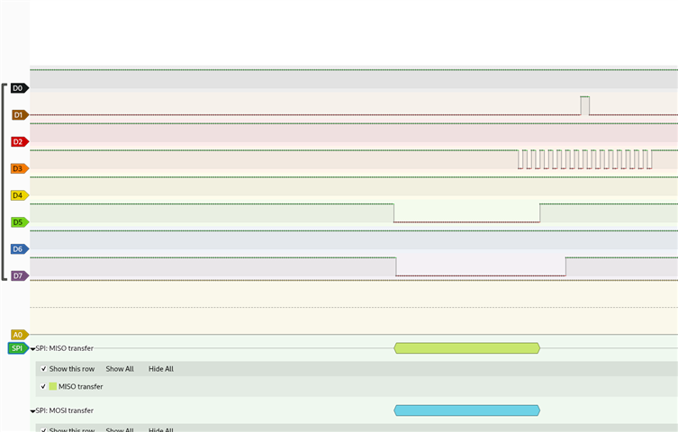
D3=CLK
D7=MISO
D1=MOSI
D5=CS
I guess there is not condition that Master has to be spi0 and slave has to be spi1, right?
Could anyone help me resolve this issue?
Thank you
Ivo