async SPI example

Dear all,

I tried this example regarding async SPI:

 https://github.com/too1/ncs-spi-master-slave-example

I also wrote overlay for this example to work on nrf52840 dongle:

&pinctrl {
    spi_master_default: spi_master_default {
        group1 {
            psels = <NRF_PSEL(SPIM_SCK, 0, 31)>,
                    <NRF_PSEL(SPIM_MOSI, 0, 29)>,
                    <NRF_PSEL(SPIM_MISO, 0, 13)>;
        };
    };

    spi_master_sleep: spi_master_sleep {
        group1 {
            psels = <NRF_PSEL(SPIM_SCK, 0, 31)>,
                    <NRF_PSEL(SPIM_MOSI, 0, 29)>,
                    <NRF_PSEL(SPIM_MISO, 0, 13)>;
            low-power-enable;
        };
    };

    spi_slave_default: spi_slave_default {
        group1 {
            psels = <NRF_PSEL(SPIS_SCK, 0, 9)>,
                    <NRF_PSEL(SPIS_MOSI, 0, 10)>,
                    <NRF_PSEL(SPIS_MISO, 1, 10)>,
                    <NRF_PSEL(SPIS_CSN, 1, 15)>;
        };
    };

    spi_slave_sleep: spi_slave_sleep {
        group1 {
            psels = <NRF_PSEL(SPIS_SCK, 0, 9)>,
                    <NRF_PSEL(SPIS_MOSI, 0, 10)>,
                    <NRF_PSEL(SPIS_MISO, 1, 10)>,
                    <NRF_PSEL(SPIS_CSN, 1, 15)>;
            low-power-enable;
        };
    };
};

my_spi_master: &spi1 {
    compatible = "nordic,nrf-spim";
    status = "okay";
    pinctrl-0 = <&spi_master_default>;
    pinctrl-1 = <&spi_master_sleep>;
    pinctrl-names = "default", "sleep";
    cs-gpios = <&gpio0 15 GPIO_ACTIVE_LOW>;
    reg_my_spi_master: spi-dev-a@0 {
        reg = <0>;
    };
};

my_spi_slave: &spi0 {
    compatible = "nordic,nrf-spis";
    status = "okay";
    pinctrl-0 = <&spi_slave_default>;
    pinctrl-1 = <&spi_slave_sleep>;
    pinctrl-names = "default", "sleep";
    def-char = <0x00>;
};

// By default uart1 will occupy P1.01 and P1.02. In order to make these pins available, disable uart1
&uart1 {
    status="disabled";
};
&i2c1{
    status="disabled";
};

I physically connected these GPIO pins together:

0, 31 with 0, 9

0, 29 with 0.10

0, 13 with 1.10

1.15 with 0.15

But when I use PulseView with dataanalyzer, I only see mangled data being send on MOSI and MISO, I think the problem could be with CS handling since the data bits are misaligned with CS being  0:
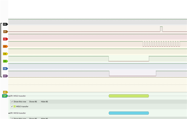
D3=CLK

D7=MISO

D1=MOSI

D5=CS

I guess there is not condition that Master has to be spi0 and slave has to be spi1, right?

Could anyone help me resolve this issue?

Thank you

Ivo

Parents Reply Children
  • Dear sir,

    thank you, actually, I set different pins instead of 0.9 and 0.10, but no change.

    I also tried this: CONFIG_NFCT_PINS_AS_GPIOS which is already DEPRECATED

    This also makes no change:

    &uicr {
        nfct-pins-as-gpios;
    };

    Anyway, I was using these pins as GPIOs in my previous projects with no necessity to manually set this:

    &uicr {
        nfct-pins-as-gpios;
    };

    I am not using NCSDK v 2.9.0, I am using Zephyr version: 3.6.99.

  • According to other resolved issues with this async SPI communication, it seems like:

    https://github.com/too1/ncs-spi-master-slave-example

    is official example. It compiles with Zephyr version: 3.6.99 very well, so I assume there is something I am missing.

    The only change I made was I wanted to rewrite the DTS in order to fit nrf52840_dongle.

    The example compiles, runs, but no data is being transferred even though it seems to be sent.

    I have all the wires connected directly without any resistor only internals (whether there are any while communicating on SPI) no capacitors so I hope there is not crossover over the cables, but those issues would be rather random I guess.

  • It is not an official example but a plaground sample done by one of my ex-colleague and I see that it is not being tested with dongle. I do not have any working dongle to even attempt to test this. 

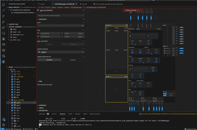
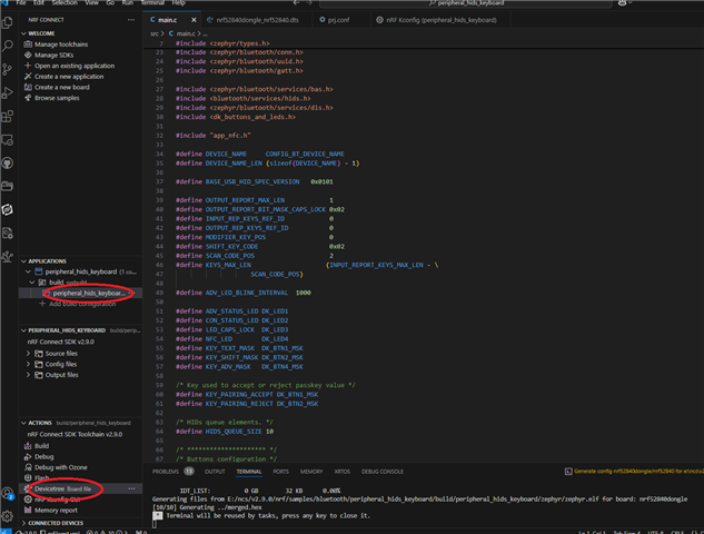
    If you are using VSCode extension for nrf connect, try to double check if the pins are indeed assigned to SPI. For some other sample I used to compile for the nrf54840 dongle, it looks something like this

    You get the option of device tree when you clock the project under build as shown in red below

  • Actually I think the pins are configured properly, all the devices in default ~/zephyrproject/zephyr/boards/nordic/nrf52840dongle/nrf52840dongle_nrf52840-pinctrl.dts with pin numbers which are now used in my SPI configuration were disabled in my nrf52840_dongle.overlay and some of the pin were just swapped fro m spi0 to spi1.

Related