async SPI example

Dear all,

I tried this example regarding async SPI:

 https://github.com/too1/ncs-spi-master-slave-example

I also wrote overlay for this example to work on nrf52840 dongle:

&pinctrl {
    spi_master_default: spi_master_default {
        group1 {
            psels = <NRF_PSEL(SPIM_SCK, 0, 31)>,
                    <NRF_PSEL(SPIM_MOSI, 0, 29)>,
                    <NRF_PSEL(SPIM_MISO, 0, 13)>;
        };
    };

    spi_master_sleep: spi_master_sleep {
        group1 {
            psels = <NRF_PSEL(SPIM_SCK, 0, 31)>,
                    <NRF_PSEL(SPIM_MOSI, 0, 29)>,
                    <NRF_PSEL(SPIM_MISO, 0, 13)>;
            low-power-enable;
        };
    };

    spi_slave_default: spi_slave_default {
        group1 {
            psels = <NRF_PSEL(SPIS_SCK, 0, 9)>,
                    <NRF_PSEL(SPIS_MOSI, 0, 10)>,
                    <NRF_PSEL(SPIS_MISO, 1, 10)>,
                    <NRF_PSEL(SPIS_CSN, 1, 15)>;
        };
    };

    spi_slave_sleep: spi_slave_sleep {
        group1 {
            psels = <NRF_PSEL(SPIS_SCK, 0, 9)>,
                    <NRF_PSEL(SPIS_MOSI, 0, 10)>,
                    <NRF_PSEL(SPIS_MISO, 1, 10)>,
                    <NRF_PSEL(SPIS_CSN, 1, 15)>;
            low-power-enable;
        };
    };
};

my_spi_master: &spi1 {
    compatible = "nordic,nrf-spim";
    status = "okay";
    pinctrl-0 = <&spi_master_default>;
    pinctrl-1 = <&spi_master_sleep>;
    pinctrl-names = "default", "sleep";
    cs-gpios = <&gpio0 15 GPIO_ACTIVE_LOW>;
    reg_my_spi_master: spi-dev-a@0 {
        reg = <0>;
    };
};

my_spi_slave: &spi0 {
    compatible = "nordic,nrf-spis";
    status = "okay";
    pinctrl-0 = <&spi_slave_default>;
    pinctrl-1 = <&spi_slave_sleep>;
    pinctrl-names = "default", "sleep";
    def-char = <0x00>;
};

// By default uart1 will occupy P1.01 and P1.02. In order to make these pins available, disable uart1
&uart1 {
    status="disabled";
};
&i2c1{
    status="disabled";
};

I physically connected these GPIO pins together:

0, 31 with 0, 9

0, 29 with 0.10

0, 13 with 1.10

1.15 with 0.15

But when I use PulseView with dataanalyzer, I only see mangled data being send on MOSI and MISO, I think the problem could be with CS handling since the data bits are misaligned with CS being  0:
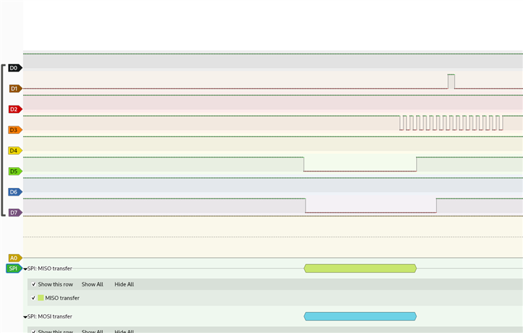
D3=CLK

D7=MISO

D1=MOSI

D5=CS

I guess there is not condition that Master has to be spi0 and slave has to be spi1, right?

Could anyone help me resolve this issue?

Thank you

Ivo

Parents
  • Hi

    Just to make sure, you said in your first reply to Susheel that you're not using the nRF Connect SDK, but Zephyr version 3.6.99. Can you confirm that you're not using the nRF Connect SDK at all or please let us know what version you're using. The sample you link to was made for and tested on nRF Connect SDK v2.5.2, and has not been tested on vanilla Zephyr. Maybe the Zephyr discord channel is a better place to ask about these issues.

    Best regards,

    Simon

Reply
  • Hi

    Just to make sure, you said in your first reply to Susheel that you're not using the nRF Connect SDK, but Zephyr version 3.6.99. Can you confirm that you're not using the nRF Connect SDK at all or please let us know what version you're using. The sample you link to was made for and tested on nRF Connect SDK v2.5.2, and has not been tested on vanilla Zephyr. Maybe the Zephyr discord channel is a better place to ask about these issues.

    Best regards,

    Simon

Children
  • I am using vanilla Zephyr,the other person who is included in unresolved issues on github repository raised an issue in 2023 experiencing the same symptoms and he was using NRF SDK.

    Anyway,despite one more bug in the example,the solution was to update to up to date Zephyr version. Zephyr 3.6.99 is probably too old,maybe from 2023?

    I am using nrf hardware because I find it excellent,but I prefer vanilla Zephyr,I still think many people benefit from resolving pure Zephyr issues as many things are shared across Zephyr and NRF SDK and to top it all still buying nrf boards or bare nrf chips.

Related