Hi,
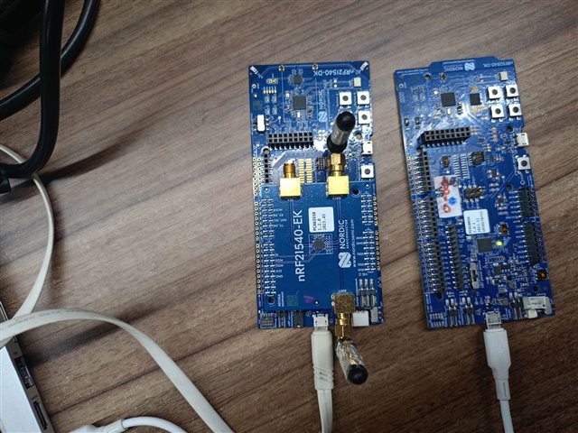
I'm working with the nRF21540 Development Bundle (DB), which includes the nRF21540 DK and nRF21540 EK. I need to use the FEM module with the GPIO+SPI interface to boost TX power.
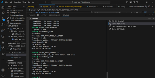
Changes Made
I added the following line to CMakeLists.txt while building the application:
set(SHIELD nrf21540ek)
I followed this guide to enable and control the FEM module with GPIO+SPI.
Device Tree Changes
nrf21540dk_nrf52840.dts
nrf_radio_fem: nrf21540_fem {
    compatible = "nordic,nrf21540-fem";
    tx-en-gpios = <&gpio0 22 GPIO_ACTIVE_HIGH>;
    rx-en-gpios = <&gpio0 19 GPIO_ACTIVE_HIGH>;
    pdn-gpios = <&gpio0 23 GPIO_ACTIVE_HIGH>;
    ant-sel-gpios = <&gpio0 20 GPIO_ACTIVE_HIGH>;
    mode-gpios = <&gpio0 17 GPIO_ACTIVE_HIGH>;
    spi-if = <&nrf_radio_fem_spi>;
    supply-voltage-mv = <3000>;
};

fem_spi: &spi3 {
    status = "okay";
    cs-gpios = <&gpio0 21 GPIO_ACTIVE_LOW>;

    pinctrl-0 = <&spi3_default>;
    pinctrl-1 = <&spi3_sleep>;
    pinctrl-names = "default", "sleep";

    nrf_radio_fem_spi: nrf21540_fem_spi@0 {
        compatible = "nordic,nrf21540-fem-spi";
        status = "okay";
        reg = <0>;
        spi-max-frequency = <8000000>;
    };
};
nrf21540dk_nrf52840-pinctrl.dtsi
spi3_default: spi3_default {
    group1 {
        psels = <NRF_PSEL(SPIM_SCK, 1, 15)>,
                <NRF_PSEL(SPIM_MISO, 1, 14)>,
                <NRF_PSEL(SPIM_MOSI, 1, 13)>;
    };
};

spi3_sleep: spi3_sleep {
    group1 {
        psels = <NRF_PSEL(SPIM_SCK, 1, 15)>,
                <NRF_PSEL(SPIM_MISO, 1, 14)>,
                <NRF_PSEL(SPIM_MOSI, 1, 13)>;
        low-power-enable;
    };
};
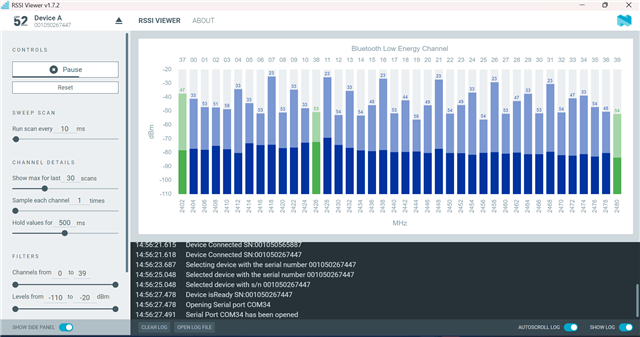
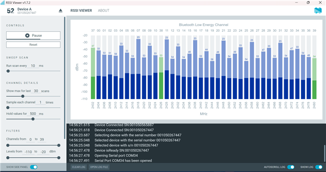
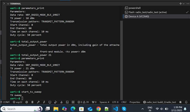
Observed Behavior
- TX power settings:
- SoC (nRF52840) TX power: 0 dBm
- Booster (nRF21540) TX power: +20 dBm
- The following changes were generated in
.config:# CONFIG_MPSL_FEM_ONLY is not set CONFIG_MPSL_FEM_ANY_SUPPORT=y CONFIG_MPSL_FEM_NRF21540_GPIO_SUPPORT=y CONFIG_MPSL_FEM_NRF21540_GPIO_SPI_SUPPORT=y CONFIG_MPSL_FEM_NCS_SUPPORTED_FEM_USED=y CONFIG_MPSL_FEM_API_AVAILABLE=y CONFIG_MPSL_FEM=y # CONFIG_MPSL_FEM_NRF21540_GPIO is not set CONFIG_MPSL_FEM_NRF21540_GPIO_SPI=y CONFIG_MPSL_FEM_NRF21540_TX_GAIN_DB=20 CONFIG_MPSL_FEM_NRF21540_TX_GAIN_DB_POUTA=20 CONFIG_MPSL_FEM_NRF21540_TX_GAIN_DB_POUTB=10 CONFIG_MPSL_FEM_NRF21540_RX_GAIN_DB=13 CONFIG_BT_CTLR_TX_PWR_ANTENNA=20 - Issue: While measuring current, I only observe 20–35 mA, which is much lower than expected. It seems like the FEM is not boosting TX power.
Questions
- Are there any additional configurations required to ensure the FEM is correctly enabled?
- How can I confirm that the FEM is active during TX?