SENT protocol based sensor configuration with nrf boards

hey there, i have a project which uses  nrf9151 with a pressures sensor from BOSCH which uses SENT protocol to transfer data, my question is

1. Is it possible to configure the SENT protocol on the nrf9151
2. if yes, how am i gonna configure what should i use?

Parents
  • The above is my implementation according to this

    SENT protocol driver using nRF Timer captures

    can someone please guide me where am i going wrong because i am unable to read any capture falling to falling edge period.

    thank you

  • I wrote some code to implement the algorithm I described, and it seems to work ok. I don't have a SENT sensor to hand, so I spoofed a test using just a Uart with 10 negative edges: {0xFF,0xB7,0xEF,0xBB, 0x7F} which decodes as SENT data A44FF4A4

    Algorithm:

    // Version using 4 peripheral Timers (most efficient) for nRF52 and nRF54:
    //
    //             |--------Fast Channel Data--------|       Optional
    // Sync  Stat    DN1   DN2   DN3   DN4   DN5   DN6   CRC    PAUSE       Description
    // ====  ===== ===== ===== ===== ===== ===== ===== ===== ========       ===========================
    //     +--------------------------------------------------------------  Edge  2: Sync
    //     |     +--------------------------------------------------------  Edge  3: Status
    //     |     |     +--------------------------------------------------  Edge  4: DN1
    //     |     |     |     +--------------------------------------------  Edge  5: DN2
    //     |     |     |     |     +--------------------------------------  Edge  6: DN3
    //     |     |     |     |     |     +--------------------------------  Edge  7: DN4
    //     |     |     |     |     |     |     +--------------------------  Edge  8: DN5
    //     |     |     |     |     |     |     |     +--------------------  Edge  9: DN6
    //     |     |     |     |     |     |     |     |     +--------------  Edge 10: CRC      Interrupt
    //     |     |     |     |     |     |     |     |     |        +-----  Edge 11: PAUSE (Optional)
    //     |     |     |     |     |     |     |     |     |        |
    // T4[0] T4[1] T4[2] T4[3] T4[4] T4[5] T1[0] T1[1] T1[2]    T1[3]  <== Timer Capture CC register Id
    //     ^     ^     ^     ^     ^     ^     ^     ^     ^        ^
    //     |     |     |     |     |     |     |     |     |        |  <== Counter compare triggers Timer capture
    //     |     |     |     |     |     |     |     |     |        |
    // C3[0] C3[1] C3[2] C3[3] C3[4] C3[5] C2[0] C2[1] C2[2]    C2[3]  <== Counter Compare CC register Id
    //     ^     ^     ^     ^     ^     ^     ^     ^     ^        ^
    //     |     |     |     |     |     |     |     |     |        |  <== Falling edge triggers counter increment
    //     |     |     |     |     |     |     |     |     |        |
    // ----+ +---+ +---+ +---+ +---+ +---+ +---+ +---+ +---+    +---+
    //     | ||||| ||||| ||||| ||||| ||||| ||||| ||||| |||||    |||||  <== Nibble Framing
    //     +-+   +-+   +-+   +-+   +-+   +-+   +-+   +-+   +----+   +-
    //     |     |     |     |     |     |     |     |     |        |
    //    56 12-27 12-27 12-27 12-27 12-27 12-27 12-27 12-27 (12-768)  <== SENT numer of Ticks range
    //     2     3     4     5     6     7     8     9    10     (11)  <== SENT Falling Edge Number
    // ====  ===== ===== ===== ===== ===== ===== ===== ===== ========
    // Sync  Stat    DN1   DN2   DN3   DN4   DN5   DN6   CRC    PAUSE
    //             |--------Fast Channel Data--------|       Optional
    
    //  Single Message
    //  {
    //    Counter EVENT      Timer Mode TASK     Nibble  Read registers
    //    =============      =================   ======  =================================
    //    Counter3-CC0  ==> capture Timer4-CC0   Sync
    //    Counter3-CC1  ==> capture Timer4-CC1   Status
    //    Counter3-CC2  ==> capture Timer4-CC2   DN1
    //    Counter3-CC3  ==> capture Timer4-CC3   DN2
    //    Counter3-CC4  ==> capture Timer4-CC4   DN3
    //    Counter3-CC5  ==> capture Timer4-CC5   DN4
    //    Counter2-CC0  ==> capture Timer1-CC0   DN5
    //    Counter2-CC1  ==> capture Timer1-CC1   DN6
    //    Counter2-CC2  ==> capture Timer1-CC2   CRC    Can start reading in interrupt here
    //    Counter2-CC3  ==> capture Timer1-CC3   PAUSE  read Timer4 CC0-CC5 and Timer1 CC0-CC3
    //  }

    Code - Proof of Concept; I used a few magic numbers as time is limited. Bare-metal but easy to translate to nRFx or (dare I say) nRFConnect:

    // PPI channels 0-19 are programmable, channels 20-31 are fixed
    #define PPI_SENT_SYNC      0 // Sync
    #define PPI_SENT_STATUS    1 // Status
    #define PPI_SENT_DN1       2 // DN1
    #define PPI_SENT_DN2       3 // DN2
    #define PPI_SENT_DN3       4 // DN3
    #define PPI_SENT_DN4       5 // DN4
    #define PPI_SENT_DN5       6 // DN5
    #define PPI_SENT_DN6       7 // DN6
    #define PPI_SENT_CRC       8 // CRC
    #define PPI_SENT_PAUSE     9 // PAUSE
    #define PPI_SENT_INPUT    10 // Input SENT signal
    #define PPI_SENT_TEST_HI  11 // Test output SENT signal high level
    #define PPI_SENT_TEST_LO  12 // Test output SENT signal low level
    #define PPI_SENT_START    13 // Use Input SENT signal to start timers
    
    // 8 GPIOTE channels available
    #define GPIOTE_SENT_INPUT 0 // Input SENT signal
    #define GPIOTE_SENT_TEST  1 // Test output SENT signal
    
    // Port pins to test SENT using PWM on output pin connected to SENT input pin
    #define PIN_SENT_INPUT    3 // Input SENT signal
    #define PIN_SENT_TEST     4 // Test output SENT signal, connect to Input SENT signal
    
    // TIMER0 is used by the RADIO, so don't use for now
    static NRF_TIMER_Type *pTimerSent_0to5   = NRF_TIMER4; // 6 x CC
    static NRF_TIMER_Type *pTimerSent_6to9   = NRF_TIMER1; // 4 x CC
    static NRF_TIMER_Type *pCounterSent_0to5 = NRF_TIMER3; // 6 x CC
    static NRF_TIMER_Type *pCounterSent_6to9 = NRF_TIMER2; // 4 x CC
    
    static void SentRxProtocol(void)
    {
       NRF_P0->OUTSET = (1 << PIN_SENT_INPUT);
       NRF_P0->OUTSET = (1 << PIN_SENT_TEST);
       // Configuration                       Direction    Input            Pullup         Drive Level      Sense Level
       // ================================    ==========   ==============   ============   ==============   =============
       NRF_P0->PIN_CNF[PIN_SENT_TEST]      = (PIN_OUTPUT | PIN_CONNECT    | PIN_PULLNONE | PIN_DRIVE_S0S1 | PIN_SENSE_OFF);
       NRF_P0->PIN_CNF[PIN_SENT_INPUT]     = (PIN_INPUT  | PIN_CONNECT    | PIN_PULLUP   | PIN_DRIVE_S0S1 | PIN_SENSE_LOW);
    
       // 32-bit timers
       pTimerSent_0to5->MODE    = TIMER_MODE_MODE_Timer;
       pTimerSent_0to5->BITMODE = TIMER_BITMODE_BITMODE_32Bit << TIMER_BITMODE_BITMODE_Pos;
       pTimerSent_6to9->MODE    = TIMER_MODE_MODE_Timer;
       pTimerSent_6to9->BITMODE = TIMER_BITMODE_BITMODE_32Bit << TIMER_BITMODE_BITMODE_Pos;
       // 1us timer period
       pTimerSent_0to5->PRESCALER = 0; // 16/2^4 -> 1MHz, 16/2^8->62.5KHz or 16uSec tick
       pTimerSent_6to9->PRESCALER = 0; // 16/2^4 -> 1MHz, 16/2^8->62.5KHz or 16uSec tick
       // Now clear timer registers
       pTimerSent_0to5->TASKS_CLEAR = 1;
       pTimerSent_6to9->TASKS_CLEAR = 1;
    
       // 32-bit counters
       pCounterSent_0to5->MODE    = TIMER_MODE_MODE_Counter;
       pCounterSent_0to5->BITMODE = TIMER_BITMODE_BITMODE_32Bit << TIMER_BITMODE_BITMODE_Pos;
       pCounterSent_6to9->MODE    = TIMER_MODE_MODE_Counter;
       pCounterSent_6to9->BITMODE = TIMER_BITMODE_BITMODE_32Bit << TIMER_BITMODE_BITMODE_Pos;
       // Prescaler not used in counter mode
       pCounterSent_0to5->PRESCALER = 0;
       pCounterSent_6to9->PRESCALER = 0;
    
       // Configure input event for count on falling edge
       NRF_GPIOTE->CONFIG[GPIOTE_SENT_INPUT] = GPIOTE_CONFIG_MODE_Event      << GPIOTE_CONFIG_MODE_Pos     |
                                               GPIOTE_CONFIG_POLARITY_HiToLo << GPIOTE_CONFIG_POLARITY_Pos |
                                               PIN_SENT_INPUT                << GPIOTE_CONFIG_PSEL_Pos     |
                                               GPIOTE_CONFIG_OUTINIT_High    << GPIOTE_CONFIG_OUTINIT_Pos;
       // Configure test output task pin for use with PWM
       NRF_GPIOTE->CONFIG[GPIOTE_SENT_TEST]  = GPIOTE_CONFIG_MODE_Task       << GPIOTE_CONFIG_MODE_Pos     |
                                               GPIOTE_CONFIG_POLARITY_LoToHi << GPIOTE_CONFIG_POLARITY_Pos |
                                               PIN_SENT_TEST                 << GPIOTE_CONFIG_PSEL_Pos     |
                                               GPIOTE_CONFIG_OUTINIT_High    << GPIOTE_CONFIG_OUTINIT_Pos;
    
       // Count on falling edge of pulse via PPI
       NRF_PPI->CH[PPI_SENT_INPUT].EEP   = (uint32_t)&NRF_GPIOTE->EVENTS_IN[GPIOTE_SENT_INPUT];
       NRF_PPI->CH[PPI_SENT_INPUT].TEP   = (uint32_t)&pCounterSent_0to5->TASKS_COUNT;
       NRF_PPI->FORK[PPI_SENT_INPUT].TEP = (uint32_t)&pCounterSent_6to9->TASKS_COUNT;
       // Start timers on falling edge of pulse via PPI
       NRF_PPI->CH[PPI_SENT_START].EEP   = (uint32_t)&NRF_GPIOTE->EVENTS_IN[GPIOTE_SENT_INPUT];
       NRF_PPI->CH[PPI_SENT_START].TEP   = (uint32_t)&pTimerSent_0to5->TASKS_START;
       NRF_PPI->FORK[PPI_SENT_START].TEP = (uint32_t)&pTimerSent_6to9->TASKS_START;
    
       // Capture elapsed time on falling edge of compare count match via PPI
       for (uint32_t CC_Index=0, PPI_Index=PPI_SENT_SYNC; CC_Index<6; CC_Index++, PPI_Index++)
       {
          // Clear edge time compare events
          pTimerSent_0to5->CC[CC_Index] = 0;
          // Set compare edge count events
          pCounterSent_0to5->CC[CC_Index] = CC_Index+1;
          // Link edge event to time capture task
          NRF_PPI->CH[PPI_Index].EEP = (uint32_t)&pCounterSent_0to5->EVENTS_COMPARE[CC_Index];  // Event
          NRF_PPI->CH[PPI_Index].TEP = (uint32_t)&pTimerSent_0to5->TASKS_CAPTURE[CC_Index]; // Task
       }
    
       // Capture elapsed time on falling edge of compare count match via PPI
       for (uint32_t CC_Index=0, PPI_Index=PPI_SENT_SYNC; CC_Index<4; CC_Index++, PPI_Index++)
       {
          // Clear edge time compare events
          pTimerSent_6to9->CC[CC_Index] = 0;
          // Set compare edge count events
          pCounterSent_6to9->CC[CC_Index] = CC_Index+1+6;
          // Link edge event to time capture task
          NRF_PPI->CH[PPI_Index+6].EEP = (uint32_t)&pCounterSent_6to9->EVENTS_COMPARE[CC_Index];  // Event
          NRF_PPI->CH[PPI_Index+6].TEP = (uint32_t)&pTimerSent_6to9->TASKS_CAPTURE[CC_Index]; // Task
      }
    
       // Enable PPI channels
       NRF_GPIOTE->EVENTS_PORT = 0;
       NRF_PPI->CHENSET = (1UL << PPI_SENT_SYNC    ) |
                          (1UL << PPI_SENT_STATUS  ) |
                          (1UL << PPI_SENT_DN1     ) |
                          (1UL << PPI_SENT_DN2     ) |
                          (1UL << PPI_SENT_DN3     ) |
                          (1UL << PPI_SENT_DN4     ) |
                          (1UL << PPI_SENT_DN5     ) |
                          (1UL << PPI_SENT_DN6     ) |
                          (1UL << PPI_SENT_CRC     ) |
                          (1UL << PPI_SENT_PAUSE   ) |
                          (1UL << PPI_SENT_INPUT   ) |
                          (1UL << PPI_SENT_TEST_HI ) |
                          (1UL << PPI_SENT_TEST_LO ) |
                          (1UL << PPI_SENT_START);;
    
       // Now clear counter registers and start counters
       pCounterSent_0to5->TASKS_CLEAR = 1;
       pCounterSent_6to9->TASKS_CLEAR = 1;
       pCounterSent_0to5->TASKS_START = 1;
       pCounterSent_6to9->TASKS_START = 1;
       // Uart test data at 230400 baud
       uint8_t SentTestPacket[] = {0xFF,0xB7,0xEF,0xBB, 0x7F};
       //
       // 1              2    3  4      5     6        7   8   9     10       11     <== Falling edge number
       // !              !    !  |      !     !        !   !   !      !        !     <== Negative-going edges
       // |-----0x00-||  |-----0x24-||  |-----0x88-||  |-----0x23-||  |-----0x40-|   <== uart 8-bit data
       // 0 11111111 11  0 11101101 11  0 11110111 11  0 11011101 11  0 11111110 1   <== uart 10-bit data with start & stop, LSB first
       //               11    4  3      3     5        5   3   4      3        8     <== uart bit count between edges with start & stop
       //              691  276 207   207   345      345 207 276    207      552     <== Received counts between edges
       //               56   22  16    16    27       27  16  22     16       44     <== Ticks Synch=56, data-12 to 27
       //                     A   4     4     F        F   4   A      4              <== SENT decoded 8-bit data 0x0-0xF
       //                     |   |     |     |        |   |   |      |
       //                     |   |     |     |        |   |   |      +------------  CRC
       //                     |   |     |     |        |   |   +-------------------  DN5
       //                     |   |     |     |        |   +-----------------------  DN5
       //                     |   |     |     |        +---------------------------  DN4
       //                     |   |     |     +------------------------------------  DN3
       //                     |   |     +------------------------------------------  DN2
       //                     |   +------------------------------------------------  DN1
       //                     +----------------------------------------------------  STATUS
       // Decodes as SENT data A44FF4A4
       //
       uartSend(SentTestPacket, sizeof(SentTestPacket));
    
       // Sync is 56 Ticks, nibbles are between 12-27 Ticks
       const uint32_t SyncTicks = 56;
       uint32_t PulseWidth[10];
       uint32_t SyncWidth = pTimerSent_0to5->CC[0];
       PulseWidth[0] = pTimerSent_0to5->CC[0];
       PulseWidth[1] = pTimerSent_0to5->CC[1] - pTimerSent_0to5->CC[0];
       PulseWidth[2] = pTimerSent_0to5->CC[2] - pTimerSent_0to5->CC[1];
       PulseWidth[3] = pTimerSent_0to5->CC[3] - pTimerSent_0to5->CC[2];
       PulseWidth[4] = pTimerSent_0to5->CC[4] - pTimerSent_0to5->CC[3];
       PulseWidth[5] = pTimerSent_0to5->CC[5] - pTimerSent_0to5->CC[4];
       PulseWidth[6] = pTimerSent_6to9->CC[0] - pTimerSent_0to5->CC[5];
       PulseWidth[7] = pTimerSent_6to9->CC[1] - pTimerSent_6to9->CC[0];
       PulseWidth[8] = pTimerSent_6to9->CC[2] - pTimerSent_6to9->CC[1];
       PulseWidth[9] = pTimerSent_6to9->CC[3] - pTimerSent_6to9->CC[2];
    
       uint8_t Nibbles[9];
       Nibbles[0] = (uint8_t)(((PulseWidth[1] * SyncTicks)) / SyncWidth) - 12;
       Nibbles[1] = (uint8_t)(((PulseWidth[2] * SyncTicks)) / SyncWidth) - 12;
       Nibbles[2] = (uint8_t)(((PulseWidth[3] * SyncTicks)) / SyncWidth) - 12;
       Nibbles[3] = (uint8_t)(((PulseWidth[4] * SyncTicks)) / SyncWidth) - 12;
       Nibbles[4] = (uint8_t)(((PulseWidth[5] * SyncTicks)) / SyncWidth) - 12;
       Nibbles[5] = (uint8_t)(((PulseWidth[6] * SyncTicks)) / SyncWidth) - 12;
       Nibbles[6] = (uint8_t)(((PulseWidth[7] * SyncTicks)) / SyncWidth) - 12;
       Nibbles[7] = (uint8_t)(((PulseWidth[8] * SyncTicks)) / SyncWidth) - 12;
       Nibbles[8] = (uint8_t)(((PulseWidth[9] * SyncTicks)) / SyncWidth) - 12;
       // Errata: [78] TIMER: High current consumption when using timer STOP task only
       //  - Workaround: Use the SHUTDOWN task after the STOP task or instead of the STOP task
       //  - this also stops the Timer from hanging after a time change
       //  - affects nRF52832, nRF52840
       pCounterSent_0to5->TASKS_SHUTDOWN = 1;
       pCounterSent_6to9->TASKS_SHUTDOWN = 1;
       pTimerSent_0to5->TASKS_SHUTDOWN = 1;
       pTimerSent_6to9->TASKS_SHUTDOWN = 1;
       // There is no STOPPED Event, and this register is read-only, so add a delay to ensure it is stopped before changes
       __DSB();
       while(1)
       {
       }
    }

  •   

    let say the signal is inverted then we can change the logic to capture rising to rising edge instead of falling to falling edge right?

    for you reference this is the datasheet of the sensor,

    0261 K01 838-000_HPS5_420bar_20160426.de.en.pdf

  • Yes the data can be inverted; try this:

    Falling edge:
       // Configure input event for count on falling edge
       NRF_GPIOTE->CONFIG[GPIOTE_SENT_INPUT] = GPIOTE_CONFIG_MODE_Event      << GPIOTE_CONFIG_MODE_Pos     |
                                               GPIOTE_CONFIG_POLARITY_HiToLo << GPIOTE_CONFIG_POLARITY_Pos |
                                               PIN_SENT_INPUT                << GPIOTE_CONFIG_PSEL_Pos     |
                                               GPIOTE_CONFIG_OUTINIT_High    << GPIOTE_CONFIG_OUTINIT_Pos;
    Rising edge:
       // Configure input event for count on rising edge
       NRF_GPIOTE->CONFIG[GPIOTE_SENT_INPUT] = GPIOTE_CONFIG_MODE_Event      << GPIOTE_CONFIG_MODE_Pos     |
                                               GPIOTE_CONFIG_POLARITY_LoToHi << GPIOTE_CONFIG_POLARITY_Pos |
                                               PIN_SENT_INPUT                << GPIOTE_CONFIG_PSEL_Pos     |
                                               GPIOTE_CONFIG_OUTINIT_Low     << GPIOTE_CONFIG_OUTINIT_Pos;
    

    Here's code for continuous reception of messages using only two timers. One timer counts SENT falling edges and the other counts time between the edges measured in 16MHz clock cycles.

    The algorithm:

    // SENT protocol
    // SENT tick ranges from 3us to about 90us, with clock-rate tolerances as high as +-25%. Each
    // nibble begins with a 5us logic low followed by a variable-width logic-high pulse
    //
    // A SENT message frame includes a sync signal followed by eight nibbles and an optional pause,
    // the latter to make up fixed-length messages
    // A nibble ranges from 12 to 27 ticks (representing 0x0 to 0xF), optional Pause is 12-768 ticks
    //
    //              |--------Fast Channel Data--------|       Optional
    // Sync  Status   DN1   DN2   DN3   DN4   DN5   DN6   CRC    PAUSE
    // ====  ====== ===== ===== ===== ===== ===== ===== ===== ========
    //  56   12-27  12-27 12-27 12-27 12-27 12-27 12-27 12-27 (12-768)  <== SENT numer of Ticks range
    //   1       2      3     4     5     6     7     8     9     (10)  <== SENT Falling Edge Number
    // C3[0] C3[1]  C3[2] C3[3] C3[4] C3[5] C3[0] C3[1] C3[2]    C3[3]  <== Counter Compare CC register Id
    // T4[0] T4[1]  T4[2] T4[3] T4[4] T4[5] T4[0] T4[1] T4[2]    T4[3]  <== Timer Capture CC register Id
    
    // Version using just 2 peripheral Timers for nRF52, nRF54 and nRF9151
    //
    //              |---------Fast Channel Data--------|        Optional
    //     Sync Stat    DN1   DN2   DN3   DN4   DN5   DN6   CRC    PAUSE  CC Edge CC Field      Read Ts Set Cs
    //     ==== ===== ===== ===== ===== ===== ===== ===== ===== ========  == ==== == =====      ======= ======
    // +------------------------------------------------------------------     1:  - Start <<-+   (First Start)
    // |      +----------------------------------------------------------- 0   2:  1 Sync     |
    // |      |     +----------------------------------------------------- 1   3:  2 Status   |
    // |      |     |     +----------------------------------------------- 2   4:  3 DN1      |
    // |      |     |     |     +----------------------------------------- 3   5:  4 DN2      | 0,1,2,3 0,1,2,3
    // |      |     |     |     |     +----------------------------------- 4   6:  5 DN3      |
    // |      |     |     |     |     |     +----------------------------- 5   7:  6 DN4      | 4,5     5=timeout
    // |      |     |     |     |     |     |     +----------------------- 0   8:  7 DN5      |
    // |      |     |     |     |     |     |     |     +----------------- 1   9:  8 DN6      |
    // |      |     |     |     |     |     |     |     |     +----------- 2  10:  9 CRC      | 0,1,2
    // |      |     |     |     |     |     |     |     |     |        +-- 3   1: 10 PAUSE >>-+ 3 (next Start)
    // |      |     |     |     |     |     |     |     |     |        |
    // ] TT2[0] T2[1] T2[2] T2[3] T2[4] T2[5] T2[0] T2[1] T2[2]    T2[3]  <== Timer Capture CC register Id
    // ^      ^     ^     ^     ^     ^     ^     ^     ^     ^        ^
    // |      |     |     |     |     |     |     |     |     |        |  <== Counter compare triggers Timer capture
    // |      |     |     |     |     |     |     |     |     |        |
    // ] CC3[0] C3[1] C3[2] C3[3] C3[4] C3[5] C3[0] C3[1] C3[2]    C3[3]  <== Counter Compare CC register Id
    // ^      ^     ^     ^     ^     ^     ^     ^     ^     ^        ^
    // |      |     |     |     |     |     |     |     |     |        |  <== Falling edge triggers counter increment
    // |      |     |     |     |     |     |     |     |     |        |
    // + +----+ +---+ +---+ +---+ +---+ +---+ +---+ +---+ +---+    +---+
    // | |    | ||||| ||||| ||||| ||||| ||||| ||||| ||||| |||||    |||||  <== Nibble Framing
    // +-+    +-+   +-+   +-+   +-+   +-+   +-+   +-+   +-+   +----+   +-
    //        |     |     |     |     |     |     |     |     |        |
    //       56 12-27 12-27 12-27 12-27 12-27 12-27 12-27 12-27 (12-768)  <== SENT numer of Ticks range
    //        2     3     4     5     6     7     8     9    10        1  <== SENT Falling Edge Number
    //     ==== ===== ===== ===== ===== ===== ===== ===== ===== ========
    //     Sync Stat    DN1   DN2   DN3   DN4   DN5   DN6   CRC    PAUSE
    //              |---------Fast Channel Data--------|

    Test messages using a hardware uart to spoof a SENT sensor:

    // Uart test data at 230400 baud
    uint8_t SentTestPacketA[] = {0xFF,0xB7,0xEF,0xBB,0x7F};
    uint8_t SentTestPacketB[] = {0xFF,0xB7,0xEF,0xDB,0x7F};
    // If continuous messages, start counter via PPI on 1st falling edge; use timeout:
    //
    // ---(N-1)->|     |<------------------------------(Message N)--------------------------->|     |<-(N+1)---   <== Message number
    //           |     |                                                                      |     |
    //       (11)      1              2    3  4      5     6        7   8   9     10      (11)      1             <== Falling edge number
    //       (10)     (Start)         1    2  3      4     5        6   7   8      9      (10)     (Start)        <== Falling edge count in pCounterSent
    //         O==/~/==O              !    !  |      !     !        !   !   !      !        O==/~/==O             <== Negative-going edges
    // -----0x7F-|     |-----0xFF-|   |-----0xB7-|   |-----0xEF-|   |-----0xBB-|   |-----0x7F-|     |-----0xFF-|  <== uart 8-bit data
    //  11111110 11    0 11111111 11  0 11101101 11  0 11110111 11  0 11011101 11  0 11111110 11    0 11111111 11 <== uart 10-bit data with start & stop, LSB first
    //         8       |             11    4  3      3     5        5   3   4      3        8       |             <== uart bit count between edges with start & stop
    //       552       |            691  276 207   207   345      345 207 276    207      552       |             <== Received 16MHz counts between edges
    //        44       |             56   22  16    16    27       27  16  22     16       44       |             <== Ticks Synch=56, data-12 to 27
    //       (20)      |            (2C)   A  4      4     F        F   4   A      4      (20)      |             <== SENT decoded 8-bit data 0x0-0xF
    //                 |              |    |  |      |     |        |   |   |      |        |       |
    //                 |              |    |  |      |     |        |   |   |      |        |       |             Edge     Counter   Timer  Message
    //                 |              |    |  |      |     |        |   |   |      |        |       |             =======  ========  =====  ========
    //                 |              |    |  |      |     |        |   |   |      |        |       +----- START  Edge  1                    N+1
    //               - |              |    |  |      |     |        |   |   |      |        +------------- PAUSE  Edge 11  CC[3]=10  CC[3]
    //               - |              |    |  |      |     |        |   |   |      +---------------------- CRC    Edge 10  CC[2]= 9  CC[2]
    //               - |              |    |  |      |     |        |   |   +----------------------------- DN5    Edge  9  CC[1]= 8  CC[1]
    //               - |              |    |  |      |     |        |   +--------------------------------- DN5    Edge  8  CC[0]= 7  CC[0]
    //               - |              |    |  |      |     |        +------------------------------------- DN4    Edge  7  CC[5]= 6  CC[5]
    //               - |              |    |  |      |     +---------------------------------------------- DN3    Edge  6  CC[4]= 5  CC[4]
    //               - |              |    |  |      +---------------------------------------------------- DN2    Edge  5  CC[3]= 4  CC[3]
    //               - |              |    |  +----------------------------------------------------------- DN1    Edge  4  CC[2]= 3  CC[2]
    //               - |              |    +-------------------------------------------------------------- STATUS Edge  3  CC[1]= 2  CC[1]
    //               - |              +------------------------------------------------------------------- SYNC   Edge  2  CC[0]= 1  CC[0]
    //               - +---------------------------------------------------------------------------------- START  Edge  1                    N
    //                MessageA Decodes as SENT data A44FF4A4
    //                MessageB Decodes as SENT data A44FF44A
    

    The SENT decoder code:

    // PPI channels 0-19 are programmable, channels 20-31 are fixed
    #define PPI_SENT_SYNC      0 // Sync
    #define PPI_SENT_STATUS    1 // Status
    #define PPI_SENT_DN1       2 // DN1
    #define PPI_SENT_DN2       3 // DN2
    #define PPI_SENT_DN3       4 // DN3
    #define PPI_SENT_DN4       5 // DN4
    #define PPI_SENT_DN5       6 // DN5
    #define PPI_SENT_DN6       7 // DN6
    #define PPI_SENT_CRC       8 // CRC
    #define PPI_SENT_PAUSE     9 // PAUSE
    #define PPI_SENT_INPUT    10 // Input SENT signal
    #define PPI_SENT_TEST_HI  11 // Test output SENT signal high level
    #define PPI_SENT_TEST_LO  12 // Test output SENT signal low level
    #define PPI_SENT_START    13 // Use Input SENT signal to start timers
    
    // 8 GPIOTE channels available
    #define GPIOTE_SENT_INPUT 0 // Input SENT signal
    #define GPIOTE_SENT_TEST  1 // Test output SENT signal
    
    // Port pins to test SENT using PWM on output pin connected to SENT input pin
    #define PIN_SENT_INPUT    3 // Input SENT signal
    #define PIN_SENT_TEST     4 // Test output SENT signal, connect to Input SENT signal
    // Set end-of-message timeout to stop timer & edge counter
    #define SENT_MESSAGE_TIMEOUT    400 // 16MHz cycles after edge 9
    
    // TIMER0 is used by the RADIO, so don't use for now
    #define SENT_COUNTER_IRQn TIMER3_IRQn
    #define SENT_TIMER_IRQn   TIMER4_IRQn
    static NRF_TIMER_Type * const pCounterSent = NRF_TIMER3; // 6 x CC
    static NRF_TIMER_Type * const pTimerSent   = NRF_TIMER4; // 6 x CC
    // Sync is 56 Ticks, nibbles are between 12-27 Ticks
    static const uint32_t SyncTicks  = 56;
    static const uint32_t Data0Ticks = 12;
    static uint32_t PulseWidth[10];
    static volatile uint32_t PulseTimes[10];
    // Define two SENT test messages
    static uint8_t CorrectNibblesA[] = {0x0A,0x04,0x04,0x0F,0x0F,0x04,0x0A,0x04};
    static uint8_t CorrectNibblesB[] = {0x0A,0x04,0x04,0x0F,0x0F,0x04,0x04,0x0A};
    static uint8_t *pCorrectNibbles = CorrectNibblesA;
    // Calculate decoded SENT 4-bit nibbles
    static uint8_t Nibbles[sizeof(CorrectNibblesA)];
    static uint32_t MessageErrorCount = 0;
    static void uartTest_SENT(const char * const Packet, const uint32_t PacketLength);
    static void SentRxInit(void);
    
    static void SentRxInit(void)
    {
       NRF_P0->OUTSET = (1 << PIN_SENT_INPUT);
       NRF_P0->OUTSET = (1 << PIN_SENT_TEST);
       // Configuration                       Direction    Input            Pullup         Drive Level      Sense Level
       // ================================    ==========   ==============   ============   ==============   =============
       NRF_P0->PIN_CNF[PIN_SENT_TEST]      = (PIN_OUTPUT | PIN_CONNECT    | PIN_PULLNONE | PIN_DRIVE_S0S1 | PIN_SENSE_OFF);
       NRF_P0->PIN_CNF[PIN_SENT_INPUT]     = (PIN_INPUT  | PIN_CONNECT    | PIN_PULLUP   | PIN_DRIVE_S0S1 | PIN_SENSE_LOW);
    
       // 32-bit timers
       pTimerSent->MODE    = TIMER_MODE_MODE_Timer;
       pTimerSent->BITMODE = TIMER_BITMODE_BITMODE_32Bit << TIMER_BITMODE_BITMODE_Pos;
       // 1us timer period
       pTimerSent->PRESCALER = 0; // 16MHz timer clock
    
       // 32-bit counters
       pCounterSent->MODE    = TIMER_MODE_MODE_Counter;
       pCounterSent->BITMODE = TIMER_BITMODE_BITMODE_32Bit << TIMER_BITMODE_BITMODE_Pos;
       // Prescaler not used in counter mode
       pCounterSent->PRESCALER = 0;
    
       // Enable edge counter IRQ on EVENTS_COMPARE[] 3 and 5
       pCounterSent->INTENSET = (TIMER_INTENSET_COMPARE2_Enabled << TIMER_INTENSET_COMPARE2_Pos) | // 2nd pass 2 registers
                                (TIMER_INTENSET_COMPARE3_Enabled << TIMER_INTENSET_COMPARE3_Pos) | // 1st pass 6 registers
                                (TIMER_INTENSET_COMPARE5_Enabled << TIMER_INTENSET_COMPARE5_Pos);  // 1st pass 2 registers
    
       // Enable edge timer IRQ on EVENTS_COMPARE[5] to act as timeout value
       pTimerSent->INTENSET = (TIMER_INTENSET_COMPARE5_Enabled << TIMER_INTENSET_COMPARE5_Pos);
    
       // Clear the counter when COMPARE5 event is triggered - doesn't work, loses capture due to 1x16MHz
       //   clock delay for PPI, so clear in interrupt
       //pCounterSent->SHORTS = (TIMER_SHORTS_COMPARE5_CLEAR_Enabled << TIMER_SHORTS_COMPARE5_CLEAR_Pos);
    
       // Set interrupt priority and enable interrupt for SENT edge counter
       NVIC_SetPriority(SENT_COUNTER_IRQn, 6);
       NVIC_ClearPendingIRQ(SENT_COUNTER_IRQn);
       __DSB();
       NVIC_EnableIRQ(SENT_COUNTER_IRQn);
    
       // Set interrupt priority and enable interrupt for SENT edge timer
       NVIC_SetPriority(SENT_TIMER_IRQn, 6);
       NVIC_ClearPendingIRQ(SENT_TIMER_IRQn);
       __DSB();
       NVIC_EnableIRQ(SENT_TIMER_IRQn);
    
       // Configure input event for count on falling edge
       NRF_GPIOTE->CONFIG[GPIOTE_SENT_INPUT] = GPIOTE_CONFIG_MODE_Event      << GPIOTE_CONFIG_MODE_Pos     |
                                               GPIOTE_CONFIG_POLARITY_HiToLo << GPIOTE_CONFIG_POLARITY_Pos |
                                               PIN_SENT_INPUT                << GPIOTE_CONFIG_PSEL_Pos     |
                                               GPIOTE_CONFIG_OUTINIT_High    << GPIOTE_CONFIG_OUTINIT_Pos;
       // Configure test output task pin for use with PWM or UART
       NRF_GPIOTE->CONFIG[GPIOTE_SENT_TEST]  = GPIOTE_CONFIG_MODE_Task       << GPIOTE_CONFIG_MODE_Pos     |
                                               GPIOTE_CONFIG_POLARITY_LoToHi << GPIOTE_CONFIG_POLARITY_Pos |
                                               PIN_SENT_TEST                 << GPIOTE_CONFIG_PSEL_Pos     |
                                               GPIOTE_CONFIG_OUTINIT_High    << GPIOTE_CONFIG_OUTINIT_Pos;
    
       // Count on falling edge of pulse via PPI
       NRF_PPI->CH[PPI_SENT_INPUT].EEP   = (uint32_t)&NRF_GPIOTE->EVENTS_IN[GPIOTE_SENT_INPUT];
       NRF_PPI->CH[PPI_SENT_INPUT].TEP   = (uint32_t)&pCounterSent->TASKS_COUNT;
       // Start timers on falling edge of pulse via PPI; repeated TASKS_START command is benign
       NRF_PPI->CH[PPI_SENT_START].EEP   = (uint32_t)&NRF_GPIOTE->EVENTS_IN[GPIOTE_SENT_INPUT];
       NRF_PPI->CH[PPI_SENT_START].TEP   = (uint32_t)&pTimerSent->TASKS_START;
       NRF_PPI->FORK[PPI_SENT_START].TEP = (uint32_t)&pCounterSent->TASKS_START;
    
       // Capture elapsed time on falling edge of compare count match via PPI
       for (uint32_t CC_Index=0, PPI_Index=PPI_SENT_SYNC; CC_Index<6; CC_Index++, PPI_Index++)
       {
          // Clear edge time compare events
          pTimerSent->CC[CC_Index] = 0;
          // Set compare edge count events from 1 to 6, repeated edge counts should also be 1 to 6
          pCounterSent->CC[CC_Index] = CC_Index+1;
          // Link edge event to time capture task
          NRF_PPI->CH[PPI_Index].EEP = (uint32_t)&pCounterSent->EVENTS_COMPARE[CC_Index]; // Event
          NRF_PPI->CH[PPI_Index].TEP = (uint32_t)&pTimerSent->TASKS_CAPTURE[CC_Index];    // Task
       }
    
       // Enable PPI channels
       NRF_GPIOTE->EVENTS_PORT = 0;
       NRF_PPI->CHENSET = (1UL << PPI_SENT_SYNC    ) | //  0
                          (1UL << PPI_SENT_STATUS  ) | //  1
                          (1UL << PPI_SENT_DN1     ) | //  2
                          (1UL << PPI_SENT_DN2     ) | //  3
                          (1UL << PPI_SENT_DN3     ) | //  4
                          (1UL << PPI_SENT_DN4     ) | //  5
                          (1UL << PPI_SENT_DN5     ) | //  6
                          (1UL << PPI_SENT_DN6     ) | //  7
                          (1UL << PPI_SENT_CRC     ) | //  8
                          (1UL << PPI_SENT_PAUSE   ) | //  9
                          (1UL << PPI_SENT_INPUT   ) | // 10
                          (1UL << PPI_SENT_TEST_HI ) | // 11
                          (1UL << PPI_SENT_TEST_LO ) | // 12
                          (1UL << PPI_SENT_START);;    // 13
       // Now clear counter and timer registers and start counters
       pCounterSent->TASKS_CLEAR = 1;
       pTimerSent->TASKS_CLEAR   = 1;
       //pCounterSent->TASKS_START = 1;
    }
    
    static void SentRxProtocolT2(void)
    {
       // Initialise Counter, Timer and GPIO ports
       SentRxInit();
       // Send test messages
       for (uint32_t i=0; i<1000; i++)
       {
          // Uart test data at 230400 baud: Toggle messages A and B
          if (i&1)
          {
             uartTest_SENT(SentTestPacketA, sizeof(SentTestPacketA));
             pCorrectNibbles = CorrectNibblesA;
          }
          else
          {
             uartTest_SENT(SentTestPacketB, sizeof(SentTestPacketB));
             pCorrectNibbles = CorrectNibblesB;
          }
    
          // Sync is 56 Ticks, nibbles are between 12-27 Ticks
          uint32_t SyncWidth = PulseTimes[0];
          PulseWidth[0] = PulseTimes[0];
          // CC[3] is only reached for edges 2 to 7, as edge 10 is actually edge 1 in the
          // next message; ie PulseTimes[9], PulseWidth[9] and Nibbles[9] PAUSE width are not reported
          for (uint32_t i=1; i<sizeof(PulseTimes)/sizeof(PulseTimes[0])-1; i++)
          {
             PulseWidth[i] = PulseTimes[i] - PulseTimes[i-1];
          }
    
          // Calculate decoded SENT 4-bit nibbles
          for (uint32_t i=0; i<sizeof(Nibbles)/sizeof(Nibbles[0]); i++)
          {
             Nibbles[i] = (uint8_t)(((PulseWidth[i+1] * SyncTicks)) / SyncWidth) - Data0Ticks;
             if (Nibbles[i] != pCorrectNibbles[i])
             {
                MessageErrorCount++;
             }
          }
          // Can use a signal to indicate when data is ready for each message
          ReceivingEdges = true;
          // Add a small delay between messages
          nrf_delay_us(100);
       }
       // Errata: [78] TIMER: High current consumption when using timer STOP task only
       //  - Workaround: Use the SHUTDOWN task after the STOP task or instead of the STOP task
       //  - this also stops the Timer from hanging after a time change
       //  - affects nRF52832, nRF52840
       pCounterSent->TASKS_SHUTDOWN = 1;
       pTimerSent->TASKS_SHUTDOWN   = 1;
       // There is no STOPPED Event, and this register is read-only, so add a delay to ensure it is stopped before changes
       __DSB();
       while(1)
       {
       }
    }
    
    // Counter CC0-5 will be used twice; edge 1 starts counter & timer, first pass uses edges 2 to 7, 2nd pass edges 8 to 10
    static volatile bool ReceivingEdges_2to7 = true;
    // Message is complete including CRC when starting next message search for START falling edge
    static volatile bool ReceivingEdges = true;
    // Set up timer CC[5] for end-of-message timeout to stop timer & edge counter, also counter
    static volatile uint32_t mTimeoutTrip = 400;
    
    // This IRQ handler will trigger every 3rd and 5th SENT falling edge
    void TIMER3_IRQHandler(void)
    {
       // Every 3rd SENT negative-going edge on first pass
       if (pCounterSent->EVENTS_COMPARE[3] == 1)
       {
          // Events 0,1,2,3 triggered by SENT edge counter have now occurred
          pCounterSent->EVENTS_COMPARE[0] = 0;
          pCounterSent->EVENTS_COMPARE[1] = 0;
          pCounterSent->EVENTS_COMPARE[2] = 0;
          pCounterSent->EVENTS_COMPARE[3] = 0;
          // CC[3] is only reached for edges 2 to 7, as edge 10 is actually edge 1 in the next message
          if (ReceivingEdges_2to7)
          {
             PulseTimes[0] = pTimerSent->CC[0];
             PulseTimes[1] = pTimerSent->CC[1];
             PulseTimes[2] = pTimerSent->CC[2];
             PulseTimes[3] = pTimerSent->CC[3];
             // Set compare edge count events from 8 to 11
             pCounterSent->CC[0] =  7;
             pCounterSent->CC[1] =  8;
             pCounterSent->CC[2] =  9;
             pCounterSent->CC[3] = 10;
             pTimerSent->CC[0] = 0;
             pTimerSent->CC[1] = 0;
             pTimerSent->CC[2] = 0;
             pTimerSent->CC[3] = 0;
          }
       }
       // Every 5th SENT negative-going edge, both 4,5 have occurred
       if (pCounterSent->EVENTS_COMPARE[5] == 1)
       {
          ReceivingEdges_2to7 = false;
          pCounterSent->EVENTS_COMPARE[4] = 0;
          pCounterSent->EVENTS_COMPARE[5] = 0;
          PulseTimes[4] = pTimerSent->CC[4];
          PulseTimes[5] = pTimerSent->CC[5];
          // Set up next timer CC[5] for end-of-message timeout to stop timer & edge counter, also counter
          mTimeoutTrip = pTimerSent->CC[2] + SENT_MESSAGE_TIMEOUT;
          pTimerSent->CC[5] = mTimeoutTrip;
       }
       // Every 2nd SENT negative-going edge on 2nd pass, starts next message search for START falling edge
       if (pCounterSent->EVENTS_COMPARE[2] == 1)
       {
          // Events 0,1,2 triggered by SENT edge counter have now occurred
          pCounterSent->EVENTS_COMPARE[2] = 0;
          if (!ReceivingEdges_2to7)
          {
             ReceivingEdges_2to7 = true;
             PulseTimes[6] = pTimerSent->CC[0];
             PulseTimes[7] = pTimerSent->CC[1];
             PulseTimes[8] = pTimerSent->CC[2];
             // CC[3] is only reached for edges 2 to 7, as edge 10 is actually edge 1 in the next message
             //PulseTimes[9] = pTimerSent->CC[3];
             pCounterSent->CC[0] =  1;
             pCounterSent->CC[1] =  2;
             pCounterSent->CC[2] =  3;
             pCounterSent->CC[3] =  4;
             pCounterSent->CC[4] =  5;
             pCounterSent->CC[5] =  6;
             //pTimerSent->TASKS_CLEAR = 1;
             pTimerSent->CC[0] = 0;
             pTimerSent->CC[1] = 0;
             pTimerSent->CC[2] = 0;
             pTimerSent->CC[3] = 0;
             pTimerSent->CC[4] = 0;
             // Edge 10 is actually edge 1 in the next message, start search for next edge which is message START
             pCounterSent->TASKS_STOP = 1;
             __DSB();
             pCounterSent->TASKS_CLEAR = 1;
             // Also stop timer as we don't require timeout protection after entire message received
             pTimerSent->TASKS_STOP = 1;
             __DSB();
             pTimerSent->TASKS_CLEAR = 1;
             // Message is complete including CRC when starting next message search for START falling edge
             ReceivingEdges = false;
         }
       }
       __DSB();
    }
    
    // This IRQ handler will trigger every 5th CC timeout value (max message length)
    void TIMER4_IRQHandler(void)
    {
       // Use CC[5] as a fall-back timeout for stop and wait for next message
       if (pTimerSent->EVENTS_COMPARE[5] == 1)
       {
          pTimerSent->EVENTS_COMPARE[5] = 0;
          if (pTimerSent->CC[5] == mTimeoutTrip)
          {
             // Timeout: Stop timer, clear counter
             pTimerSent->TASKS_STOP    = 1;
             pTimerSent->TASKS_CLEAR   = 1;
             pCounterSent->TASKS_STOP  = 1;
             pCounterSent->TASKS_CLEAR = 1;
             // Clear the timeout register ready for next (5+1)th edge capture
             pTimerSent->CC[5] = 0;
             // Message is complete including CRC when starting next message search for START falling edge
             ReceivingEdges = false;
          }
       }
    }

    The UART code for spoofing SENT test messages:

    #define TX_PIN_NUMBER   PIN_SENT_TEST // PIN_FEATHER_TXD // P0.25
    #define RX_PIN_NUMBER   24            // PIN_FEATHER_RXD // P0.24
    
    static void uartTest_SENT(const char * const Packet, const uint32_t PacketLength)
    {
       // Power on UART
       *(volatile uint32_t *)(NRF_UARTE0_BASE+0xFFC) = 1; //  UARTE Power Enable
       __DSB();
       if (!NRF_UARTE0->ENABLE)
       {
          nrf_gpio_pin_set(TX_PIN_NUMBER);
          // Configuration            Direction                Input                          Pullup               Drive Level        Sense Level
          // =====================    =======================  =============================  ===================  =================  =======================
          nrf_gpio_cfg(TX_PIN_NUMBER, NRF_GPIO_PIN_DIR_OUTPUT, NRF_GPIO_PIN_INPUT_DISCONNECT, NRF_GPIO_PIN_PULLUP, NRF_GPIO_PIN_H0H1, NRF_GPIO_PIN_NOSENSE);
          nrf_gpio_cfg(RX_PIN_NUMBER, NRF_GPIO_PIN_DIR_INPUT,  NRF_GPIO_PIN_INPUT_CONNECT,    NRF_GPIO_PIN_PULLUP, NRF_GPIO_PIN_H0H1, NRF_GPIO_PIN_NOSENSE);
          // Configure the UARTE with no flow control, no parity bit and 230400 baud rate
          NRF_UARTE0->CONFIG = (UART_CONFIG_HWFC_Disabled   << UART_CONFIG_HWFC_Pos) | (UART_CONFIG_PARITY_Excluded << UART_CONFIG_PARITY_Pos);
          NRF_UARTE0->BAUDRATE = UARTE_BAUDRATE_BAUDRATE_Baud230400 << UARTE_BAUDRATE_BAUDRATE_Pos;
          // Select TX and RX pins
          NRF_UARTE0->PSEL.TXD = TX_PIN_NUMBER;
          NRF_UARTE0->PSEL.RXD = RX_PIN_NUMBER;
          // Enable the UART (starts using the TX/RX pins)
          NRF_UARTE0->ENABLE = UARTE_ENABLE_ENABLE_Enabled << UARTE_ENABLE_ENABLE_Pos;
       }
       // Clear CTS which is always set on init regardless of HWFC
       NRF_UARTE0->EVENTS_CTS = 0;
       // Configure transmit buffer and start the transfer
       NRF_UARTE0->TXD.MAXCNT = PacketLength;
       NRF_UARTE0->TXD.PTR    = (uint32_t)Packet;
       NRF_UARTE0->TASKS_STARTTX = 1;
       // Wait until the transfer is complete
       while (NRF_UARTE0->EVENTS_ENDTX == 0)
       {
       }
       // Stop the UART TX
       NRF_UARTE0->TASKS_STOPTX = 1;
       __DSB();
       // Wait until we receive the stopped event
       while (NRF_UARTE0->EVENTS_TXSTOPPED == 0);
       NRF_UARTE0->EVENTS_ENDTX = 0;
       NRF_UARTE0->EVENTS_TXSTOPPED = 0;
       NRF_UARTE0->EVENTS_TXSTARTED = 0;
       // Disable the UARTE (pins are now available for other use)
       NRF_UARTE0->ENABLE = UARTE_ENABLE_ENABLE_Disabled << UARTE_ENABLE_ENABLE_Pos;
       __DSB();
       // Power off UART
       *(volatile uint32_t *)(NRF_UARTE0_BASE+0xFFC) = 0; //  UARTE Power Enable
    }
    

  • #include <stdbool.h>
    #include <stdint.h>
    
    #include "nrf.h"
    #include "nordic_common.h"
    #include "boards.h"
    #include "nrf_delay.h"
    #include "nrfx_gpiote.h"
    #include "nrf_log.h"
    #include "nrf_log_ctrl.h"
    #include "nrf_log_default_backends.h"
    
    #define PPI_SENT_SYNC      0 // Sync
    #define PPI_SENT_STATUS    1 // Status
    #define PPI_SENT_DN1       2 // DN1
    #define PPI_SENT_DN2       3 // DN2
    #define PPI_SENT_DN3       4 // DN3
    #define PPI_SENT_DN4       5 // DN4
    #define PPI_SENT_DN5       6 // DN5
    #define PPI_SENT_DN6       7 // DN6
    #define PPI_SENT_CRC       8 // CRC
    #define PPI_SENT_PAUSE     9 // PAUSE
    #define PPI_SENT_INPUT    10 // Input SENT signal
    #define PPI_SENT_TEST_HI  11 // Test output SENT signal high level
    #define PPI_SENT_TEST_LO  12 // Test output SENT signal low level
    #define PPI_SENT_START    13 // Use Input SENT signal to start timers
    
    // 8 GPIOTE channels available
    #define GPIOTE_SENT_INPUT 0 // Input SENT signal
    #define GPIOTE_SENT_TEST  1 // Test output SENT signal
    
    // Port pins to test SENT using PWM on output pin connected to SENT input pin
    #define PIN_SENT_INPUT    3 // Input SENT signal
    #define PIN_SENT_TEST     4 // Test output SENT signal, connect to Input SENT signal
    // Set end-of-message timeout to stop timer & edge counter
    #define SENT_MESSAGE_TIMEOUT    400 // 16MHz cycles after edge 9
    
    // TIMER0 is used by the RADIO, so don't use for now
    #define SENT_COUNTER_IRQn TIMER3_IRQn
    #define SENT_TIMER_IRQn   TIMER4_IRQn
    static NRF_TIMER_Type * const pCounterSent = NRF_TIMER3; // 6 x CC
    static NRF_TIMER_Type * const pTimerSent   = NRF_TIMER4; // 6 x CC
    
    // Sync is 56 Ticks, nibbles are between 12-27 Ticks
    static const uint32_t SyncTicks  = 56;
    static const uint32_t Data0Ticks = 12;
    static uint32_t PulseWidth[10];
    static volatile uint32_t PulseTimes[10];
    
    // Define two SENT test messages
    static uint8_t CorrectNibblesA[] = {0x0A,0x04,0x04,0x0F,0x0F,0x04,0x0A,0x04};
    static uint8_t CorrectNibblesB[] = {0x0A,0x04,0x04,0x0F,0x0F,0x04,0x04,0x0A};
    static uint8_t *pCorrectNibbles = CorrectNibblesA;
    
    // Calculate decoded SENT 4-bit nibbles
    static uint8_t Nibbles[sizeof(CorrectNibblesA)];
    static uint32_t MessageErrorCount = 0;
    
    
    static void SentRxInit(void)
    {
       NRF_P0->OUTSET = (1 << PIN_SENT_INPUT);
       NRF_P0->OUTSET = (1 << PIN_SENT_TEST);
       // Configuration                       Direction    Input            Pullup         Drive Level      Sense Level
       // ================================    ==========   ==============   ============   ==============   =============
       //NRF_P0->PIN_CNF[PIN_SENT_TEST]      = (PIN_OUTPUT | PIN_CONNECT    | PIN_PULLNONE | PIN_DRIVE_S0S1 | PIN_SENSE_OFF);
       //NRF_P0->PIN_CNF[PIN_SENT_INPUT]     = (PIN_INPUT  | PIN_CONNECT    | PIN_PULLUP   | PIN_DRIVE_S0S1 | PIN_SENSE_LOW);
    
       // Configuration for PIN_SENT_TEST (output)
        NRF_P0->PIN_CNF[PIN_SENT_TEST] = (GPIO_PIN_CNF_DIR_Output << GPIO_PIN_CNF_DIR_Pos) |
                                     (GPIO_PIN_CNF_INPUT_Connect << GPIO_PIN_CNF_INPUT_Pos) |
                                     (GPIO_PIN_CNF_PULL_Disabled << GPIO_PIN_CNF_PULL_Pos) |
                                     (GPIO_PIN_CNF_DRIVE_S0S1 << GPIO_PIN_CNF_DRIVE_Pos) |
                                     (GPIO_PIN_CNF_SENSE_Disabled << GPIO_PIN_CNF_SENSE_Pos);
    
        // Configuration for PIN_SENT_INPUT (input with pull-up)
        NRF_P0->PIN_CNF[PIN_SENT_INPUT] = (GPIO_PIN_CNF_DIR_Input << GPIO_PIN_CNF_DIR_Pos) |
                                      (GPIO_PIN_CNF_INPUT_Connect << GPIO_PIN_CNF_INPUT_Pos) |
                                      (GPIO_PIN_CNF_PULL_Pullup << GPIO_PIN_CNF_PULL_Pos) |
                                      (GPIO_PIN_CNF_DRIVE_S0S1 << GPIO_PIN_CNF_DRIVE_Pos) |
                                      (GPIO_PIN_CNF_SENSE_Low << GPIO_PIN_CNF_SENSE_Pos);
    
       // 32-bit timers
       pTimerSent->MODE    = TIMER_MODE_MODE_Timer;
       pTimerSent->BITMODE = TIMER_BITMODE_BITMODE_32Bit << TIMER_BITMODE_BITMODE_Pos;
       // 1us timer period
       pTimerSent->PRESCALER = 0; // 16MHz timer clock
    
       // 32-bit counters
       pCounterSent->MODE    = TIMER_MODE_MODE_Counter;
       pCounterSent->BITMODE = TIMER_BITMODE_BITMODE_32Bit << TIMER_BITMODE_BITMODE_Pos;
       // Prescaler not used in counter mode
       pCounterSent->PRESCALER = 0;
    
       // Enable edge counter IRQ on EVENTS_COMPARE[] 3 and 5
       pCounterSent->INTENSET = (TIMER_INTENSET_COMPARE2_Enabled << TIMER_INTENSET_COMPARE2_Pos) | // 2nd pass 2 registers
                                (TIMER_INTENSET_COMPARE5_Enabled << TIMER_INTENSET_COMPARE5_Pos) | // 1st pass 6 registers
                                (TIMER_INTENSET_COMPARE5_Enabled << TIMER_INTENSET_COMPARE5_Pos);  // 1st pass 2 registers
    
       // Enable edge timer IRQ on EVENTS_COMPARE[5] to act as timeout value
       pTimerSent->INTENSET = (TIMER_INTENSET_COMPARE5_Enabled << TIMER_INTENSET_COMPARE5_Pos);
    
       // Clear the counter when COMPARE5 event is triggered - doesn't work, loses capture due to 1x16MHz
       //   clock delay for PPI, so clear in interrupt
       //pCounterSent->SHORTS = (TIMER_SHORTS_COMPARE5_CLEAR_Enabled << TIMER_SHORTS_COMPARE5_CLEAR_Pos);
    
       // Set interrupt priority and enable interrupt for SENT edge counter
       NVIC_SetPriority(SENT_COUNTER_IRQn, 6);
       NVIC_ClearPendingIRQ(SENT_COUNTER_IRQn);
       __DSB();
       NVIC_EnableIRQ(SENT_COUNTER_IRQn);
    
       // Set interrupt priority and enable interrupt for SENT edge timer
       NVIC_SetPriority(SENT_TIMER_IRQn, 6);
       NVIC_ClearPendingIRQ(SENT_TIMER_IRQn);
       __DSB();
       NVIC_EnableIRQ(SENT_TIMER_IRQn);
    
       // Configure input event for count on rising edge
       NRF_GPIOTE->CONFIG[GPIOTE_SENT_INPUT] = GPIOTE_CONFIG_MODE_Event      << GPIOTE_CONFIG_MODE_Pos     |
                                               GPIOTE_CONFIG_POLARITY_LoToHi << GPIOTE_CONFIG_POLARITY_Pos |
                                               PIN_SENT_INPUT                << GPIOTE_CONFIG_PSEL_Pos     |
                                               GPIOTE_CONFIG_OUTINIT_Low     << GPIOTE_CONFIG_OUTINIT_Pos;
       // Configure test output task pin for use with PWM or UART
       NRF_GPIOTE->CONFIG[GPIOTE_SENT_TEST]  = GPIOTE_CONFIG_MODE_Task       << GPIOTE_CONFIG_MODE_Pos     |
                                               GPIOTE_CONFIG_POLARITY_LoToHi << GPIOTE_CONFIG_POLARITY_Pos |
                                               PIN_SENT_TEST                 << GPIOTE_CONFIG_PSEL_Pos     |
                                               GPIOTE_CONFIG_OUTINIT_High    << GPIOTE_CONFIG_OUTINIT_Pos;
    
       // Count on falling edge of pulse via PPI
       NRF_PPI->CH[PPI_SENT_INPUT].EEP   = (uint32_t)&NRF_GPIOTE->EVENTS_IN[GPIOTE_SENT_INPUT];
       NRF_PPI->CH[PPI_SENT_INPUT].TEP   = (uint32_t)&pCounterSent->TASKS_COUNT;
       // Start timers on falling edge of pulse via PPI; repeated TASKS_START command is benign
       NRF_PPI->CH[PPI_SENT_START].EEP   = (uint32_t)&NRF_GPIOTE->EVENTS_IN[GPIOTE_SENT_INPUT];
       NRF_PPI->CH[PPI_SENT_START].TEP   = (uint32_t)&pTimerSent->TASKS_START;
       NRF_PPI->FORK[PPI_SENT_START].TEP = (uint32_t)&pCounterSent->TASKS_START;
    
       // Capture elapsed time on falling edge of compare count match via PPI
       for (uint32_t CC_Index=0, PPI_Index=PPI_SENT_SYNC; CC_Index<6; CC_Index++, PPI_Index++)
       {
          // Clear edge time compare events
          pTimerSent->CC[CC_Index] = 0;
          // Set compare edge count events from 1 to 6, repeated edge counts should also be 1 to 6
          pCounterSent->CC[CC_Index] = CC_Index+1;
          // Link edge event to time capture task
          NRF_PPI->CH[PPI_Index].EEP = (uint32_t)&pCounterSent->EVENTS_COMPARE[CC_Index]; // Event
          NRF_PPI->CH[PPI_Index].TEP = (uint32_t)&pTimerSent->TASKS_CAPTURE[CC_Index];    // Task
       }
    
       // Enable PPI channels
       NRF_GPIOTE->EVENTS_PORT = 0;
       NRF_PPI->CHENSET = (1UL << PPI_SENT_SYNC    ) | //  0
                          (1UL << PPI_SENT_STATUS  ) | //  1
                          (1UL << PPI_SENT_DN1     ) | //  2
                          (1UL << PPI_SENT_DN2     ) | //  3
                          (1UL << PPI_SENT_DN3     ) | //  4
                          (1UL << PPI_SENT_DN4     ) | //  5
                          (1UL << PPI_SENT_DN5     ) | //  6
                          (1UL << PPI_SENT_DN6     ) | //  7
                          (1UL << PPI_SENT_CRC     ) | //  8
                          (1UL << PPI_SENT_PAUSE   ) | //  9
                          (1UL << PPI_SENT_INPUT   ) | // 10
                          (1UL << PPI_SENT_TEST_HI ) | // 11
                          (1UL << PPI_SENT_TEST_LO ) | // 12
                          (1UL << PPI_SENT_START);;    // 13
       // Now clear counter and timer registers and start counters
       pCounterSent->TASKS_CLEAR = 1;
       pTimerSent->TASKS_CLEAR   = 1;
       //pCounterSent->TASKS_START = 1;
    }
    
    // Counter CC0-5 will be used twice; edge 1 starts counter & timer, first pass uses edges 2 to 7, 2nd pass edges 8 to 10
    static volatile bool ReceivingEdges_2to7 = true;
    // Set up timer CC[5] for end-of-message timeout to stop timer & edge counter, also counter
    static volatile uint32_t mTimeoutTrip = 400;
    
    void TIMER3_IRQHandler(void)
    {
       // Every 3rd SENT negative-going edge on first pass
       if (pCounterSent->EVENTS_COMPARE[3] == 1)
       {
          // Events 0,1,2,3 triggered by SENT edge counter have now occurred
          pCounterSent->EVENTS_COMPARE[0] = 0;
          pCounterSent->EVENTS_COMPARE[1] = 0;
          pCounterSent->EVENTS_COMPARE[2] = 0;
          pCounterSent->EVENTS_COMPARE[3] = 0;
          // CC[3] is only reached for edges 2 to 7, as edge 10 is actually edge 1 in the next message
          if (ReceivingEdges_2to7)
          {
             PulseTimes[0] = pTimerSent->CC[0];
             PulseTimes[1] = pTimerSent->CC[1];
             PulseTimes[2] = pTimerSent->CC[2];
             PulseTimes[3] = pTimerSent->CC[3];
             // Set compare edge count events from 8 to 11
             pCounterSent->CC[0] =  7;
             pCounterSent->CC[1] =  8;
             pCounterSent->CC[2] =  9;
             pCounterSent->CC[3] = 10;
             pTimerSent->CC[0] = 0;
             pTimerSent->CC[1] = 0;
             pTimerSent->CC[2] = 0;
             pTimerSent->CC[3] = 0;
          }
       }
       // Every 5th SENT negative-going edge, both 4,5 have occurred
       if (pCounterSent->EVENTS_COMPARE[5] == 1)
       {
          ReceivingEdges_2to7 = false;
          pCounterSent->EVENTS_COMPARE[4] = 0;
          pCounterSent->EVENTS_COMPARE[5] = 0;
          PulseTimes[4] = pTimerSent->CC[4];
          PulseTimes[5] = pTimerSent->CC[5];
          // Set up next timer CC[5] for end-of-message timeout to stop timer & edge counter, also counter
          mTimeoutTrip = pTimerSent->CC[2] + SENT_MESSAGE_TIMEOUT;
          pTimerSent->CC[5] = mTimeoutTrip;
       }
       // Every 2nd SENT negative-going edge on 2nd pass, starts next message search for START falling edge
       if (pCounterSent->EVENTS_COMPARE[2] == 1)
       {
          // Events 0,1,2 triggered by SENT edge counter have now occurred
          pCounterSent->EVENTS_COMPARE[2] = 0;
          if (!ReceivingEdges_2to7)
          {
             ReceivingEdges_2to7 = true;
             PulseTimes[6] = pTimerSent->CC[0];
             PulseTimes[7] = pTimerSent->CC[1];
             PulseTimes[8] = pTimerSent->CC[2];
             // CC[3] is only reached for edges 2 to 7, as edge 10 is actually edge 1 in the next message
             //PulseTimes[9] = pTimerSent->CC[3];
             pCounterSent->CC[0] =  1;
             pCounterSent->CC[1] =  2;
             pCounterSent->CC[2] =  3;
             pCounterSent->CC[3] =  4;
             pCounterSent->CC[4] =  5;
             pCounterSent->CC[5] =  6;
             //pTimerSent->TASKS_CLEAR = 1;
             pTimerSent->CC[0] = 0;
             pTimerSent->CC[1] = 0;
             pTimerSent->CC[2] = 0;
             pTimerSent->CC[3] = 0;
             pTimerSent->CC[4] = 0;
             // Edge 10 is actually edge 1 in the next message, start search for next edge which is message START
             pCounterSent->TASKS_STOP = 1;
             __DSB();
             pCounterSent->TASKS_CLEAR = 1;
             // Also stop timer as we don't require timeout protection after entire message received
             pTimerSent->TASKS_STOP = 1;
             __DSB();
             pTimerSent->TASKS_CLEAR = 1;
         }
       }
       __DSB();
    }
    
    void TIMER4_IRQHandler(void)
    {
       // Use CC[5] as a fall-back timeout for stop and wait for next message
       if (pTimerSent->EVENTS_COMPARE[5] == 1)
       {
          pTimerSent->EVENTS_COMPARE[5] = 0;
          if (pTimerSent->CC[5] == mTimeoutTrip)
          {
             // Timeout: Stop timer, clear counter
             pTimerSent->TASKS_STOP    = 1;
             pTimerSent->TASKS_CLEAR   = 1;
             pCounterSent->TASKS_STOP  = 1;
             pCounterSent->TASKS_CLEAR = 1;
             // Clear the timeout register ready for next (5+1)th edge capture
             pTimerSent->CC[5] = 0;
          }
       }
    }
    
    static void log_init(void)
    {
        ret_code_t err_code = NRF_LOG_INIT(NULL);
        APP_ERROR_CHECK(err_code);
    
        NRF_LOG_DEFAULT_BACKENDS_INIT();
    }
    
    static void process_sent_data(void)
    {
        // Calculate pulse widths
        for (int i = 0; i < 9; i++) {
            PulseWidth[i] = PulseTimes[i+1] - PulseTimes[i];
        }
    
        // Log the pulse widths
        NRF_LOG_INFO("Pulse Widths:");
        for (int i = 0; i < 9; i++) {
            NRF_LOG_INFO("Pulse %d: %d ticks", i, PulseWidth[i]);
        }
    
        NRF_LOG_FLUSH();
    }
    
    int main(void)
    {
        log_init();
        SentRxInit();
    
        NRF_LOG_INFO("SENT Signal Measurement Started");
        NRF_LOG_FLUSH();
    
        while (true)
        {
            // Wait for a complete SENT message
            while (ReceivingEdges_2to7) {
                __WFE();
            }
    
            // Process the received data
            process_sent_data();
    
            // Reset for next message
            ReceivingEdges_2to7 = true;
    
            nrf_delay_ms(10);
        }
    }


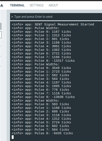
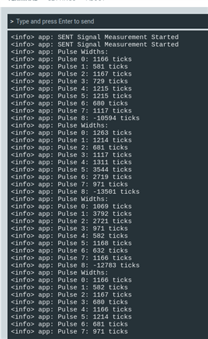
    the results are still same not satisfying.

  • Couple of issue; first this test for messages does not work as it assumes the message ends on edge 7 instead of edge 9:

            // Wait for a complete SENT message
            while (ReceivingEdges_2to7) {
                __WFE();
            }
    

    Try replacing with:

            // Wait for a complete SENT message
            while (ReceivingEdges) {
                __WFE();
            }
    

    and add a new bool:

    // Counter CC0-5 will be used twice; edge 1 starts counter & timer, first pass uses edges 2 to 7, 2nd pass edges 8 to 10
    static volatile bool ReceivingEdges_2to7 = true;
    
    // Message is complete including CRC when starting next message search for START falling edge
    static volatile bool ReceivingEdges = true;
    
    use in 3 places:
    1: TIMER3_IRQHandler
       // Every 2nd SENT negative-going edge on 2nd pass, starts next message search for START falling edge
       if (pCounterSent->EVENTS_COMPARE[2] == 1)
       {
          // Events 0,1,2 triggered by SENT edge counter have now occurred
          pCounterSent->EVENTS_COMPARE[2] = 0;
          if (!ReceivingEdges_2to7)
          {
             ReceivingEdges_2to7 = true;
             // Message is complete including CRC when starting next message search for START falling edge
             ReceivingEdges = false;
    
    2: TIMER4_IRQHandler
          if (pTimerSent->CC[5] == mTimeoutTrip)
          {
             // Message is complete including CRC when starting next message search for START falling edge
             ReceivingEdges = false;
             // Timeout: Stop timer, clear counter
    
    3: main
            // Wait for a complete SENT message
            while (ReceivingEdges) {         <<==!
                __WFE();
            }
    
            // Process the received data
            process_sent_data();
    
            // Reset for next message
            ReceivingEdges = true;          <<==!

    Correct this typo:

    Typo: 2,3,5 not 2,5,5
       // Enable edge counter IRQ on EVENTS_COMPARE[] 3 and 5
       pCounterSent->INTENSET = (TIMER_INTENSET_COMPARE2_Enabled << TIMER_INTENSET_COMPARE2_Pos) | // 2nd pass 2 registers
                                (TIMER_INTENSET_COMPARE3_Enabled << TIMER_INTENSET_COMPARE3_Pos) | // 1st pass 6 registers
                                (TIMER_INTENSET_COMPARE5_Enabled << TIMER_INTENSET_COMPARE5_Pos);  // 1st pass 2 registers
    

    Do you have a copy of the full SENT standard? The Bosch sensor data refers to that without mentioning polarity:

    SENT standard (SENT Standard J2716 Jan 2010 [1]; SENT = Single Edge Nibble Transmission for Automotive Applications).

    Edit: I still think the Bosch data is inverted. You might find this study interesting: diva2:1162587.pdf

  • unfortunately not i don't have the SAEj2716 2010 standard they didn't provide us that. but i have the SAEj2716 2016 standard.

    here it is

    sent-single-edge-nibble-transmission-for-automotive-applications-j2716-2016-04_compress.pdf


    About the signal you are right its inverted and we are trying to communicate this to bosch, will let you know once we get a response.

Reply Children


  • #include <stdbool.h>
    #include <stdint.h>
    
    #include "nrf.h"
    #include "nordic_common.h"
    #include "boards.h"
    #include "nrf_delay.h"
    #include "nrfx_gpiote.h"
    #include "nrf_log.h"
    #include "nrf_log_ctrl.h"
    #include "nrf_log_default_backends.h"
    
    #define PPI_SENT_SYNC      0 // Sync
    #define PPI_SENT_STATUS    1 // Status
    #define PPI_SENT_DN1       2 // DN1
    #define PPI_SENT_DN2       3 // DN2
    #define PPI_SENT_DN3       4 // DN3
    #define PPI_SENT_DN4       5 // DN4
    #define PPI_SENT_DN5       6 // DN5
    #define PPI_SENT_DN6       7 // DN6
    #define PPI_SENT_CRC       8 // CRC
    #define PPI_SENT_PAUSE     9 // PAUSE
    #define PPI_SENT_INPUT    10 // Input SENT signal
    #define PPI_SENT_TEST_HI  11 // Test output SENT signal high level
    #define PPI_SENT_TEST_LO  12 // Test output SENT signal low level
    #define PPI_SENT_START    13 // Use Input SENT signal to start timers
    
    // 8 GPIOTE channels available
    #define GPIOTE_SENT_INPUT 0 // Input SENT signal
    #define GPIOTE_SENT_TEST  1 // Test output SENT signal
    
    // Port pins to test SENT using PWM on output pin connected to SENT input pin
    #define PIN_SENT_INPUT    3 // Input SENT signal
    #define PIN_SENT_TEST     4 // Test output SENT signal, connect to Input SENT signal
    // Set end-of-message timeout to stop timer & edge counter
    #define SENT_MESSAGE_TIMEOUT    400 // 16MHz cycles after edge 9
    
    // TIMER0 is used by the RADIO, so don't use for now
    #define SENT_COUNTER_IRQn TIMER3_IRQn
    #define SENT_TIMER_IRQn   TIMER4_IRQn
    static NRF_TIMER_Type * const pCounterSent = NRF_TIMER3; // 6 x CC
    static NRF_TIMER_Type * const pTimerSent   = NRF_TIMER4; // 6 x CC
    
    // Sync is 56 Ticks, nibbles are between 12-27 Ticks
    static const uint32_t SyncTicks  = 56;
    static const uint32_t Data0Ticks = 12;
    static uint32_t PulseWidth[10];
    static volatile uint32_t PulseTimes[10];
    
    // Define two SENT test messages
    static uint8_t CorrectNibblesA[] = {0x0A,0x04,0x04,0x0F,0x0F,0x04,0x0A,0x04};
    static uint8_t CorrectNibblesB[] = {0x0A,0x04,0x04,0x0F,0x0F,0x04,0x04,0x0A};
    static uint8_t *pCorrectNibbles = CorrectNibblesA;
    
    // Calculate decoded SENT 4-bit nibbles
    static uint8_t Nibbles[sizeof(CorrectNibblesA)];
    static uint32_t MessageErrorCount = 0;
    
    
    static void SentRxInit(void)
    {
       NRF_P0->OUTSET = (1 << PIN_SENT_INPUT);
       NRF_P0->OUTSET = (1 << PIN_SENT_TEST);
       // Configuration                       Direction    Input            Pullup         Drive Level      Sense Level
       // ================================    ==========   ==============   ============   ==============   =============
       //NRF_P0->PIN_CNF[PIN_SENT_TEST]      = (PIN_OUTPUT | PIN_CONNECT    | PIN_PULLNONE | PIN_DRIVE_S0S1 | PIN_SENSE_OFF);
       //NRF_P0->PIN_CNF[PIN_SENT_INPUT]     = (PIN_INPUT  | PIN_CONNECT    | PIN_PULLUP   | PIN_DRIVE_S0S1 | PIN_SENSE_LOW);
    
       // Configuration for PIN_SENT_TEST (output)
        NRF_P0->PIN_CNF[PIN_SENT_TEST] = (GPIO_PIN_CNF_DIR_Output << GPIO_PIN_CNF_DIR_Pos) |
                                     (GPIO_PIN_CNF_INPUT_Connect << GPIO_PIN_CNF_INPUT_Pos) |
                                     (GPIO_PIN_CNF_PULL_Disabled << GPIO_PIN_CNF_PULL_Pos) |
                                     (GPIO_PIN_CNF_DRIVE_S0S1 << GPIO_PIN_CNF_DRIVE_Pos) |
                                     (GPIO_PIN_CNF_SENSE_Disabled << GPIO_PIN_CNF_SENSE_Pos);
    
        // Configuration for PIN_SENT_INPUT (input with pull-up)
        NRF_P0->PIN_CNF[PIN_SENT_INPUT] = (GPIO_PIN_CNF_DIR_Input << GPIO_PIN_CNF_DIR_Pos) |
                                      (GPIO_PIN_CNF_INPUT_Connect << GPIO_PIN_CNF_INPUT_Pos) |
                                      (GPIO_PIN_CNF_PULL_Pullup << GPIO_PIN_CNF_PULL_Pos) |
                                      (GPIO_PIN_CNF_DRIVE_S0S1 << GPIO_PIN_CNF_DRIVE_Pos) |
                                      (GPIO_PIN_CNF_SENSE_Low << GPIO_PIN_CNF_SENSE_Pos);
    
       // 32-bit timers
       pTimerSent->MODE    = TIMER_MODE_MODE_Timer;
       pTimerSent->BITMODE = TIMER_BITMODE_BITMODE_32Bit << TIMER_BITMODE_BITMODE_Pos;
       // 1us timer period
       pTimerSent->PRESCALER = 0; // 16MHz timer clock
    
       // 32-bit counters
       pCounterSent->MODE    = TIMER_MODE_MODE_Counter;
       pCounterSent->BITMODE = TIMER_BITMODE_BITMODE_32Bit << TIMER_BITMODE_BITMODE_Pos;
       // Prescaler not used in counter mode
       pCounterSent->PRESCALER = 0;
    
       // Enable edge counter IRQ on EVENTS_COMPARE[] 3 and 5
       pCounterSent->INTENSET = (TIMER_INTENSET_COMPARE2_Enabled << TIMER_INTENSET_COMPARE2_Pos) | // 2nd pass 2 registers
                                (TIMER_INTENSET_COMPARE3_Enabled << TIMER_INTENSET_COMPARE3_Pos) | // 1st pass 6 registers
                                (TIMER_INTENSET_COMPARE5_Enabled << TIMER_INTENSET_COMPARE5_Pos);  // 1st pass 2 registers
    
       // Enable edge timer IRQ on EVENTS_COMPARE[5] to act as timeout value
       pTimerSent->INTENSET = (TIMER_INTENSET_COMPARE5_Enabled << TIMER_INTENSET_COMPARE5_Pos);
    
       // Clear the counter when COMPARE5 event is triggered - doesn't work, loses capture due to 1x16MHz
       //   clock delay for PPI, so clear in interrupt
       //pCounterSent->SHORTS = (TIMER_SHORTS_COMPARE5_CLEAR_Enabled << TIMER_SHORTS_COMPARE5_CLEAR_Pos);
    
       // Set interrupt priority and enable interrupt for SENT edge counter
       NVIC_SetPriority(SENT_COUNTER_IRQn, 6);
       NVIC_ClearPendingIRQ(SENT_COUNTER_IRQn);
       __DSB();
       NVIC_EnableIRQ(SENT_COUNTER_IRQn);
    
       // Set interrupt priority and enable interrupt for SENT edge timer
       NVIC_SetPriority(SENT_TIMER_IRQn, 6);
       NVIC_ClearPendingIRQ(SENT_TIMER_IRQn);
       __DSB();
       NVIC_EnableIRQ(SENT_TIMER_IRQn);
    
       // Configure input event for count on rising edge
       NRF_GPIOTE->CONFIG[GPIOTE_SENT_INPUT] = GPIOTE_CONFIG_MODE_Event      << GPIOTE_CONFIG_MODE_Pos     |
                                               GPIOTE_CONFIG_POLARITY_LoToHi << GPIOTE_CONFIG_POLARITY_Pos |
                                               PIN_SENT_INPUT                << GPIOTE_CONFIG_PSEL_Pos     |
                                               GPIOTE_CONFIG_OUTINIT_Low     << GPIOTE_CONFIG_OUTINIT_Pos;
       // Configure test output task pin for use with PWM or UART
       NRF_GPIOTE->CONFIG[GPIOTE_SENT_TEST]  = GPIOTE_CONFIG_MODE_Task       << GPIOTE_CONFIG_MODE_Pos     |
                                               GPIOTE_CONFIG_POLARITY_LoToHi << GPIOTE_CONFIG_POLARITY_Pos |
                                               PIN_SENT_TEST                 << GPIOTE_CONFIG_PSEL_Pos     |
                                               GPIOTE_CONFIG_OUTINIT_High    << GPIOTE_CONFIG_OUTINIT_Pos;
    
       // Count on falling edge of pulse via PPI
       NRF_PPI->CH[PPI_SENT_INPUT].EEP   = (uint32_t)&NRF_GPIOTE->EVENTS_IN[GPIOTE_SENT_INPUT];
       NRF_PPI->CH[PPI_SENT_INPUT].TEP   = (uint32_t)&pCounterSent->TASKS_COUNT;
       // Start timers on falling edge of pulse via PPI; repeated TASKS_START command is benign
       NRF_PPI->CH[PPI_SENT_START].EEP   = (uint32_t)&NRF_GPIOTE->EVENTS_IN[GPIOTE_SENT_INPUT];
       NRF_PPI->CH[PPI_SENT_START].TEP   = (uint32_t)&pTimerSent->TASKS_START;
       NRF_PPI->FORK[PPI_SENT_START].TEP = (uint32_t)&pCounterSent->TASKS_START;
    
       // Capture elapsed time on falling edge of compare count match via PPI
       for (uint32_t CC_Index=0, PPI_Index=PPI_SENT_SYNC; CC_Index<6; CC_Index++, PPI_Index++)
       {
          // Clear edge time compare events
          pTimerSent->CC[CC_Index] = 0;
          // Set compare edge count events from 1 to 6, repeated edge counts should also be 1 to 6
          pCounterSent->CC[CC_Index] = CC_Index+1;
          // Link edge event to time capture task
          NRF_PPI->CH[PPI_Index].EEP = (uint32_t)&pCounterSent->EVENTS_COMPARE[CC_Index]; // Event
          NRF_PPI->CH[PPI_Index].TEP = (uint32_t)&pTimerSent->TASKS_CAPTURE[CC_Index];    // Task
       }
    
       // Enable PPI channels
       NRF_GPIOTE->EVENTS_PORT = 0;
       NRF_PPI->CHENSET = (1UL << PPI_SENT_SYNC    ) | //  0
                          (1UL << PPI_SENT_STATUS  ) | //  1
                          (1UL << PPI_SENT_DN1     ) | //  2
                          (1UL << PPI_SENT_DN2     ) | //  3
                          (1UL << PPI_SENT_DN3     ) | //  4
                          (1UL << PPI_SENT_DN4     ) | //  5
                          (1UL << PPI_SENT_DN5     ) | //  6
                          (1UL << PPI_SENT_DN6     ) | //  7
                          (1UL << PPI_SENT_CRC     ) | //  8
                          (1UL << PPI_SENT_PAUSE   ) | //  9
                          (1UL << PPI_SENT_INPUT   ) | // 10
                          (1UL << PPI_SENT_TEST_HI ) | // 11
                          (1UL << PPI_SENT_TEST_LO ) | // 12
                          (1UL << PPI_SENT_START);;    // 13
       // Now clear counter and timer registers and start counters
       pCounterSent->TASKS_CLEAR = 1;
       pTimerSent->TASKS_CLEAR   = 1;
       //pCounterSent->TASKS_START = 1;
    }
    
    // Counter CC0-5 will be used twice; edge 1 starts counter & timer, first pass uses edges 2 to 7, 2nd pass edges 8 to 10
    static volatile bool ReceivingEdges_2to7 = true;
    
    // Message is complete including CRC when starting next message search for START falling edge
    static volatile bool ReceivingEdges = true;
    
    // Set up timer CC[5] for end-of-message timeout to stop timer & edge counter, also counter
    static volatile uint32_t mTimeoutTrip = 400;
    
    void TIMER3_IRQHandler(void)
    {
       // Every 3rd SENT negative-going edge on first pass
       if (pCounterSent->EVENTS_COMPARE[3] == 1)
       {
          // Events 0,1,2,3 triggered by SENT edge counter have now occurred
          pCounterSent->EVENTS_COMPARE[0] = 0;
          pCounterSent->EVENTS_COMPARE[1] = 0;
          pCounterSent->EVENTS_COMPARE[2] = 0;
          pCounterSent->EVENTS_COMPARE[3] = 0;
          // CC[3] is only reached for edges 2 to 7, as edge 10 is actually edge 1 in the next message
          if (ReceivingEdges_2to7)
          {
             PulseTimes[0] = pTimerSent->CC[0];
             PulseTimes[1] = pTimerSent->CC[1];
             PulseTimes[2] = pTimerSent->CC[2];
             PulseTimes[3] = pTimerSent->CC[3];
             // Set compare edge count events from 8 to 11
             pCounterSent->CC[0] =  7;
             pCounterSent->CC[1] =  8;
             pCounterSent->CC[2] =  9;
             pCounterSent->CC[3] = 10;
             pTimerSent->CC[0] = 0;
             pTimerSent->CC[1] = 0;
             pTimerSent->CC[2] = 0;
             pTimerSent->CC[3] = 0;
          }
       }
       // Every 5th SENT negative-going edge, both 4,5 have occurred
       if (pCounterSent->EVENTS_COMPARE[5] == 1)
       {
          ReceivingEdges_2to7 = false;
          pCounterSent->EVENTS_COMPARE[4] = 0;
          pCounterSent->EVENTS_COMPARE[5] = 0;
          PulseTimes[4] = pTimerSent->CC[4];
          PulseTimes[5] = pTimerSent->CC[5];
          // Set up next timer CC[5] for end-of-message timeout to stop timer & edge counter, also counter
          mTimeoutTrip = pTimerSent->CC[2] + SENT_MESSAGE_TIMEOUT;
          pTimerSent->CC[5] = mTimeoutTrip;
       }
       // Every 2nd SENT negative-going edge on 2nd pass, starts next message search for START falling edge
       if (pCounterSent->EVENTS_COMPARE[2] == 1)
       {
          // Events 0,1,2 triggered by SENT edge counter have now occurred
          pCounterSent->EVENTS_COMPARE[2] = 0;
          if (!ReceivingEdges_2to7)
          {
             ReceivingEdges_2to7 = true;
             // Message is complete including CRC when starting next message search for START falling edge
             ReceivingEdges = false;
             PulseTimes[6] = pTimerSent->CC[0];
             PulseTimes[7] = pTimerSent->CC[1];
             PulseTimes[8] = pTimerSent->CC[2];
             // CC[3] is only reached for edges 2 to 7, as edge 10 is actually edge 1 in the next message
             //PulseTimes[9] = pTimerSent->CC[3];
             pCounterSent->CC[0] =  1;
             pCounterSent->CC[1] =  2;
             pCounterSent->CC[2] =  3;
             pCounterSent->CC[3] =  4;
             pCounterSent->CC[4] =  5;
             pCounterSent->CC[5] =  6;
             //pTimerSent->TASKS_CLEAR = 1;
             pTimerSent->CC[0] = 0;
             pTimerSent->CC[1] = 0;
             pTimerSent->CC[2] = 0;
             pTimerSent->CC[3] = 0;
             pTimerSent->CC[4] = 0;
             // Edge 10 is actually edge 1 in the next message, start search for next edge which is message START
             pCounterSent->TASKS_STOP = 1;
             __DSB();
             pCounterSent->TASKS_CLEAR = 1;
             // Also stop timer as we don't require timeout protection after entire message received
             pTimerSent->TASKS_STOP = 1;
             __DSB();
             pTimerSent->TASKS_CLEAR = 1;
         }
       }
       __DSB();
    }
    
    void TIMER4_IRQHandler(void)
    {
       // Use CC[5] as a fall-back timeout for stop and wait for next message
       if (pTimerSent->EVENTS_COMPARE[5] == 1)
       {
          pTimerSent->EVENTS_COMPARE[5] = 0;
          if (pTimerSent->CC[5] == mTimeoutTrip)
          {
             // Message is complete including CRC when starting next message search for START falling edge
             ReceivingEdges = false;
             // Timeout: Stop timer, clear counter
             pTimerSent->TASKS_STOP    = 1;
             pTimerSent->TASKS_CLEAR   = 1;
             pCounterSent->TASKS_STOP  = 1;
             pCounterSent->TASKS_CLEAR = 1;
             // Clear the timeout register ready for next (5+1)th edge capture
             pTimerSent->CC[5] = 0;
          }
       }
    }
    
    static void log_init(void)
    {
        ret_code_t err_code = NRF_LOG_INIT(NULL);
        APP_ERROR_CHECK(err_code);
    
        NRF_LOG_DEFAULT_BACKENDS_INIT();
    }
    
    static void process_sent_data(void)
    {
        // Calculate pulse widths
        for (int i = 0; i < 9; i++) {
            PulseWidth[i] = PulseTimes[i+1] - PulseTimes[i];
        }
    
        // Log the pulse widths
        NRF_LOG_INFO("Pulse Widths:");
        for (int i = 0; i < 9; i++) {
            NRF_LOG_INFO("Pulse %d: %d ticks", i, PulseWidth[i]);
        }
    
        NRF_LOG_FLUSH();
    }
    
    int main(void)
    {
        log_init();
        SentRxInit();
    
        NRF_LOG_INFO("SENT Signal Measurement Started");
        NRF_LOG_FLUSH();
    
        while (true)
        {
            // Wait for a complete SENT message
            while (ReceivingEdges) {
                __WFE();
            }
    
            // Process the received data
            process_sent_data();
    
            // Reset for next message
            ReceivingEdges = true; 
    
            nrf_delay_ms(10);
        }
    }


    is this code okay for rising to rising edge detection and counting?

    the results are some how i think okay it all depends on now the tick time use by the sensor module which i am not sure if its really 3us, as in the SENT standard this tick can be from 3us to 90us so the reason i am getting all these values high could be that the tick time is greater then 3us.


    but then on the other hand the signal receive through logic analyzer is somehow okay with just the issue of its inverted so its really confusing whats happening.....

  • The code looks ok, and the auto-scale of the clock using the SYNC value will allow the use of any tick time. Try adding some code to convert edge times to actual data values:

          // Sync is 56 Ticks, nibbles are between 12-27 Ticks
          uint32_t SyncWidth = PulseTimes[0];
          PulseWidth[0] = PulseTimes[0];
          // CC[3] is only reached for edges 2 to 7, as edge 10 is actually edge 1 in the
          // next message; ie PulseTimes[9], PulseWidth[9] and Nibbles[9] PAUSE width are not reported
          for (uint32_t i=1; i<sizeof(PulseTimes)/sizeof(PulseTimes[0])-1; i++)
          {
             PulseWidth[i] = PulseTimes[i] - PulseTimes[i-1];
          }
    
          // Calculate decoded SENT 4-bit nibbles
          for (uint32_t i=0; i<sizeof(Nibbles)/sizeof(Nibbles[0]); i++)
          {
             Nibbles[i] = (uint8_t)(((PulseWidth[i+1] * SyncTicks)) / SyncWidth) - Data0Ticks;
             if (Nibbles[i] != pCorrectNibbles[i])
             {
                MessageErrorCount++;
             }
          }
          // Can use a signal to indicate when data is ready for each message
          ReceivingEdges = true;
    

    Running test code over 10,000 messages spoofing with a uart I get no errors. One difference with a real sensor is the sensor starts asynchronously and some method of aligning reception is required, either a timeout after a period of no signal or simple search for the correct-width sync pulse.

    I found some arduino code here, haven't had time to look at it BlinxFox/sent

Related