
I would like to know which pins are available for nRF5340 on Thingy91 X on the debug board interface.
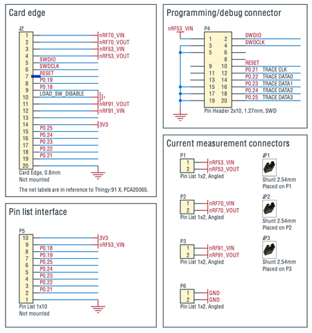
I was looking into PCA64165_Schematic_And_PCB.pdf and PCA20065_Schematic_And_PCB.pdf of Thingy91_X - Hardware files 1_0_0.
Below image shows the nRF9151 pins in red and nRF5340 pins in black.
According to below image, it should be P0.08 to P0.12 for nRF5340, which matches to the above stating TRACE xxx.
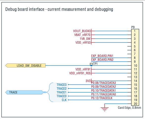
What confuses me is that P0.08 to P0.11 are used for SPI.
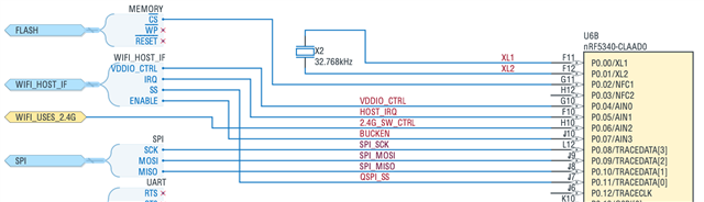
SPI is shared with nRF9151 yet on other pins for the nRF9151 that connected to the debug board.
These drawings are very confusing for me. Can you please confirm the pins?
Side questions: What is the meaning of the two different shadings of red?
I want to use a spare pin for I2S out for LEDs using "worldsemi,ws2812-i2s". I got this working from the nRF9151 (using P0.22, P0.21 didn't work), but from the nRF5340 it does not work since I probably don't configure the correct pins.
&pinctrl {
    // Connection to LED strip
	i2s0_default_alt:  i2s0_default_alt {
		group1 {
			psels =
				<NRF_PSEL(I2S_SCK_M, 0, 16)>, // pin not connected
				<NRF_PSEL(I2S_LRCK_M, 0, 21)>, // pin not connected
				<NRF_PSEL(I2S_SDOUT, 0, 12)>,
				<NRF_PSEL(I2S_SDIN, 0, 19)>; // pin not connected
		};
	};
};

