Trouble Flashing to ublox ANNA-B402 on Custom Board

I have implemented a ublox ANNA-B402 on a custom board and am trying to flash code using the debug out header (P19). I am using Segger Embedded Studio and am flashing code just fine to the dev board (simple blinky code). I have VDD, SWDIO, SWCLK, SWO, and GRD connected to/from my custom board to P19:

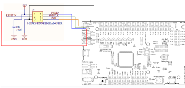
I am seeing 3.3V at VDD on P19 and continuity between the ground on my custom board and the dev kit. I currently have SW6 positioned for DEFAULT and SW9 positioned for USB, I am powering the custom board from an external source, and have verified the ANNA is getting 3.3V. I can not establish a J-Link connection with the custom board. Any help or insight would be greatly appreciated. 

Parents
  • Thanks for the pics Christopher.  It shows me you have the newer DKs where we are now using our nRF5340 as the OBD.

    There was a change in how the kit determines what programming port to use when we moved from the older OBDs to the nRF5340 OBDs. If you have followed the instructions to the letter and have ALL the signals wired then it should work seamlessly but if you have not wired all/done something not standard then you may see unexpected behavior.

    Recommendation is to check out the nRF52 DK user guide on our documentation site, docs.nordicsemi.com/.../ext_programming_support_P19.html, and see if your setup is correct according to this user guide.  Apologies but we have not updated all of the nRF52xxx DK user guides yet.  The new nRF52833DKs have the same circuitry for external programming as new nRF52 DKs.

    Looks like this will require using the 10 pin format instead of the 6 pin format.

    Let me know if that fixes the issue.

    Thanks

    Mike

  • Based on the nRF52dk doc the only change I made was connecting pin 3 on P19 to my external board's ground. I still do not have it working. The SWD0_SW0 pin has the description: "The Serial Wire Output (SWO) line is not used for programming and debugging over SWD". Should I keep it disconnected or does it not matter? 

  • You are correct that you do not need the SWD0_SW0 (Serial Wire Output).

    By grounding pin 3 on P19, you are telling the nRF52833-DK to program your external board instead of the nRF52833 on the DK.

    The only thing I can see that might be an issue now is whether you have the same supply voltage on both boards.

    • The voltage on the external board must match that of the DK.
    • When the DK is powered through the USB connector, the voltage is 3V.

    If you that does not get you working, I can try duplicating your set up but I do not have a new revision of the nRF52833-DK like you are using.  But I do have a new version of the nRF52840-DK which should be basically the same thing for this functionality.

    Thanks

Reply
  • You are correct that you do not need the SWD0_SW0 (Serial Wire Output).

    By grounding pin 3 on P19, you are telling the nRF52833-DK to program your external board instead of the nRF52833 on the DK.

    The only thing I can see that might be an issue now is whether you have the same supply voltage on both boards.

    • The voltage on the external board must match that of the DK.
    • When the DK is powered through the USB connector, the voltage is 3V.

    If you that does not get you working, I can try duplicating your set up but I do not have a new revision of the nRF52833-DK like you are using.  But I do have a new version of the nRF52840-DK which should be basically the same thing for this functionality.

    Thanks

Children
No Data
Related