
Hi all,
I need to generate two 1 MHz signals with opposite phases. However once I configure the decode mode as "Individual" I don't have output signals. In case of "Common" mode, I have two same output signals but this is not what I want. Under debugger I have different register values especially for EVENTS_SEQxxx.
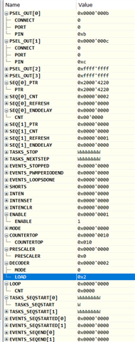
1. Individual mode
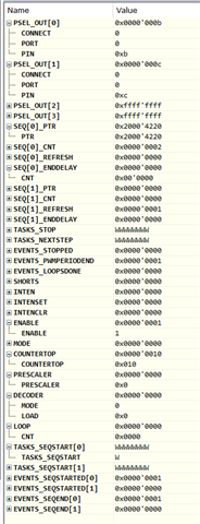
2. Common mode
Here is the code:
/* PWM for 1 MHz square signal generation */
#define PWM_OUTPUT_PIN_0 11//22//4  // First 1 MHz signal
#define PWM_OUTPUT_PIN_1 12//23//5  // Second 1 MHz signal (inverted)

// Define PWM sequence for complementary 1 MHz signals
// static uint16_t pwm_seq[2] = {8, 8};  // 50% duty cycle for both channels
static uint16_t pwm_seq[4] = {
    8,               // CH0: Normal (rising edge)
    8 | (1 << 15),   // CH1: Inverted (falling edge)
};


void io_pwm_init(void) {

    nrf_clock_hfclk_t HF_CLk;

    /* Check if the high frequency crystal isn't enabled */
    HF_CLk = nrf_clock_hf_src_get();
    if (HF_CLk != NRF_CLOCK_HFCLK_HIGH_ACCURACY)
    {
        /* Enable the high frequency clock */
        NRF_CLOCK->EVENTS_HFCLKSTARTED = 0;
        NRF_CLOCK->TASKS_HFCLKSTART    = 1;

        while (NRF_CLOCK->EVENTS_HFCLKSTARTED == 0)
        {
            /* Do nothing while waiting for the clock to start */
        }
    }

    // Select GPIOs for PWM output
    NRF_PWM0->PSEL.OUT[0] = PWM_OUTPUT_PIN_0 | (PWM_PSEL_OUT_CONNECT_Connected << PWM_PSEL_OUT_CONNECT_Pos);
    NRF_PWM0->PSEL.OUT[1] = PWM_OUTPUT_PIN_1 | (PWM_PSEL_OUT_CONNECT_Connected << PWM_PSEL_OUT_CONNECT_Pos);

    // Set PWM mode (Up mode)
    NRF_PWM0->MODE = PWM_MODE_UPDOWN_Up << PWM_MODE_UPDOWN_Pos;

    // Set the prescaler keep 16 MHz PWM base clock
    NRF_PWM0->PRESCALER = PWM_PRESCALER_PRESCALER_DIV_1; // 16 MHz clock

    // Set the maximum count value for 1 MHz frequency
    NRF_PWM0->COUNTERTOP = 16;  // 16 MHz / 16 = 1 MHz

    // Assign sequence to PWM
    NRF_PWM0->SEQ[0].PTR = (uint32_t)pwm_seq;
    NRF_PWM0->SEQ[0].CNT = 2;
    NRF_PWM0->SEQ[0].REFRESH = 0;
    NRF_PWM0->SEQ[0].ENDDELAY = 0;

    // Configure decoder to use individual values
    NRF_PWM0->DECODER = PWM_DECODER_LOAD_Individual << PWM_DECODER_LOAD_Pos;
    //NRF_PWM0->DECODER = PWM_DECODER_LOAD_Common << PWM_DECODER_LOAD_Pos;

    // Enable the PWM peripheral
    NRF_PWM0->ENABLE = 1;

//    NRF_PWM0->LOOP = 0; // Ensure it does not stop after one cycle
    NRF_PWM0->LOOP = (PWM_LOOP_CNT_Msk & (0 << PWM_LOOP_CNT_Pos));  // Infinite looping


    // Start the PWM sequence
    NRF_PWM0->TASKS_SEQSTART[0] = 1;
}
Thanks for your help.
BR,
Hulu
