Review PCB design for nrf54l15 for Matter over Thread use

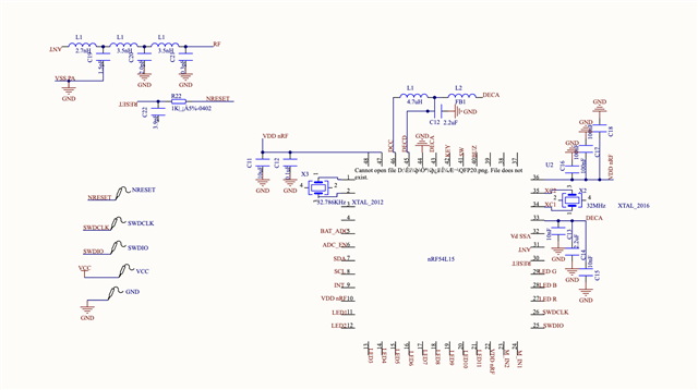
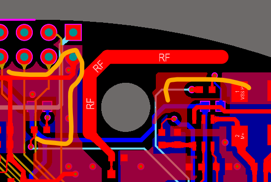
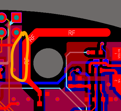
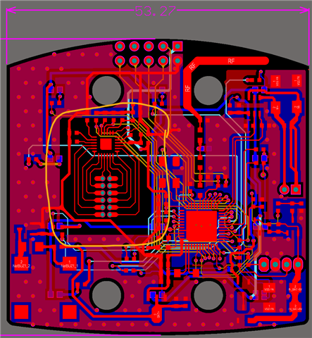
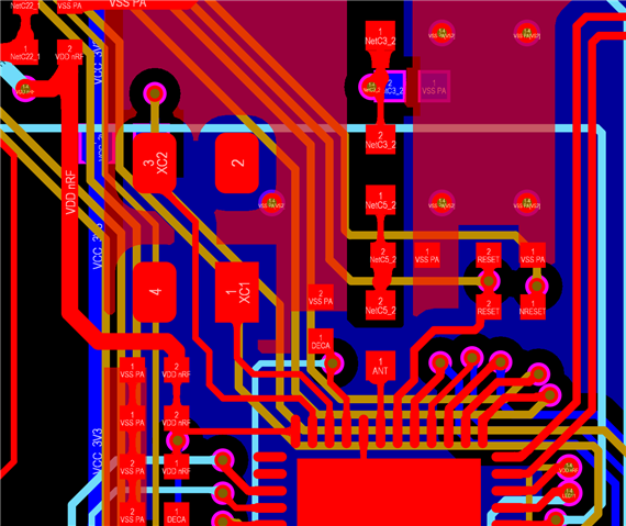
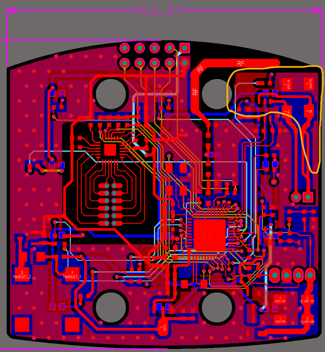
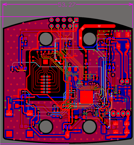
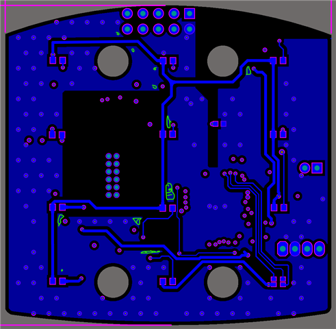
Hi, I would like to have some suggestions on my PCBA design for nrf54L15 chip. Please review it and give some suggestion moving forward. I am making this PCB to use this with matter-over-thread products. Since nrf54L15 is a pretty new product, I couldn't find many reference designs online. I mostly used the reference designs provided by Nordic but have been struggle on the programming port design. Also does nordic have any recommendation on which Antenna I should use for this design?

Thanks

Parents
  • Hi Eric,

    I have reviewed the design. Just remember that 

    • "For the device to function properly, exposed die pad (pin 49) must be connected to ground (VSS, pins 32 and 44)".
    For programming external boards using the nRF54L15 DK's debug port, the external board must:

    Please let us know if you have any specific questions regarding programming the board.

    The rest of the design looks good.

    does nordic have any recommendation on which Antenna I should use for this design?

    Choosing the optimal antenna depends higly on the type of application, budget and available board space.

    • Monopole quarter wave PCB antenna: This is easy to make and tune, requiring only one shunt component for impedance matching plus the antenna length. It needs about 23 mm of space and a minimum 5 mm clearance to the ground plane. This is a good option if you have sufficient board space. Make the antenna a little longer than required and cut it shorter  on the prototype when tuning it. See General PCB design guidelines for nRF52 series.
    • Off-the-shelf chip antennas: There are many chip antennas available that work well with Nordic devices. These are particularly useful for size-constrained designs. When selecting a chip antenna, pay close attention to the recommended mounting instructions from the antenna vendor. Check out our reference designs Thingy:91/9X/53 for some examples.

    Nordic offers hardware reviews and tuning of the radio matching network and the antenna. Just create a private ticket on DevZone. 

    Also see nWP_017 - Antenna tuning.

Reply
  • Hi Eric,

    I have reviewed the design. Just remember that 

    • "For the device to function properly, exposed die pad (pin 49) must be connected to ground (VSS, pins 32 and 44)".
    For programming external boards using the nRF54L15 DK's debug port, the external board must:

    Please let us know if you have any specific questions regarding programming the board.

    The rest of the design looks good.

    does nordic have any recommendation on which Antenna I should use for this design?

    Choosing the optimal antenna depends higly on the type of application, budget and available board space.

    • Monopole quarter wave PCB antenna: This is easy to make and tune, requiring only one shunt component for impedance matching plus the antenna length. It needs about 23 mm of space and a minimum 5 mm clearance to the ground plane. This is a good option if you have sufficient board space. Make the antenna a little longer than required and cut it shorter  on the prototype when tuning it. See General PCB design guidelines for nRF52 series.
    • Off-the-shelf chip antennas: There are many chip antennas available that work well with Nordic devices. These are particularly useful for size-constrained designs. When selecting a chip antenna, pay close attention to the recommended mounting instructions from the antenna vendor. Check out our reference designs Thingy:91/9X/53 for some examples.

    Nordic offers hardware reviews and tuning of the radio matching network and the antenna. Just create a private ticket on DevZone. 

    Also see nWP_017 - Antenna tuning.

Children
No Data
Related