I2C functions don’t work, but using the I2C shell does

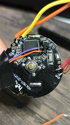
I bought a tiny board on Aliexpress from HolyIOT. It comes with an nRF52832 and an LIS2DH12 accelerometer. The silkscreen on the board says HOLYIOT-21011-v1.0.

This schematic is not from the exact same board but is nearly identical. Sorry for the bad quality, it's the best I could find.
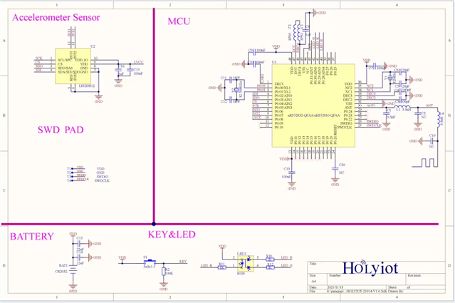
Holyiot_21014_schematic

My goal is to obtain readings from the LIS2DH12 accelerometer. I tried using SPI first, but I had no luck.

Then, I tried with I2C since I'm more familiar with it. I paid attention to the accelerometer pins to enable the power supply, set it to I2C mode, and configure SA0.

  gpio_is_ready_dt(&i2c_on); //LIS2DH pin 2 (CS)
  gpio_pin_configure_dt(&i2c_on, GPIO_OUTPUT_ACTIVE);
  gpio_pin_set_dt(&i2c_on, 1);

  gpio_is_ready_dt(&lsb_sens); //LIS2DH pin 3 (SA0) -> i2c addr = 0x19
  gpio_pin_configure_dt(&lsb_sens, GPIO_OUTPUT_ACTIVE);
  gpio_pin_set_dt(&lsb_sens, 1);

  gpio_is_ready_dt(&supply); //LIS2DH pin 9 and 10 (VDD)
  gpio_pin_configure_dt(&supply, GPIO_OUTPUT_ACTIVE);
  gpio_pin_set_dt(&supply, 1);

With both SPI and I2C, I tried using Zephyr's official driver for this sensor, but I couldn't get it to work, apparently due to errors while reading the chip ID (WHO_AM_I register).

So, I then tried using the I2C shell to check this register manually. Here is the capture:

As you can see, the I2C scanner found the correct address of the sensor (0x19). I was also able to query the WHO_AM_I (0x0F) register, and the sensor responded correctly with 0x33, as stated in the datasheet.

At that point, I stopped trying with the sensor driver and decided to use the bare I2C functions instead. Here is an example:

  const struct device *dev = device_get_binding("i2c@40004000");

  uint8_t reg_addr[2] = {0x0f, 1};
  uint8_t data[2] = {0,0};

  if (dev == NULL) {
		printk("No device found\n");
		return;
	}

  ret = i2c_write(dev, reg_addr, 1, 0x19);
  if(ret != 0){
    printk("Failed to write from I2C device address %02x at Reg. %02x \n\r", dev_i2c.addr, reg_addr[0]);
  }
  ret = i2c_read(dev, data, 1, 0x19);

  if(ret != 0){
    printk("Failed to read from I2C device address %02x at Reg. %02x \n\r", dev_i2c.addr, reg_addr[0]);
  }
  printk("Byte: %02x\n", data[0]);

Here is another try:

#define I2C1_NODE DT_NODELABEL(mysensor)
static const struct i2c_dt_spec dev_i2c = I2C_DT_SPEC_GET(I2C1_NODE);

(...)

uint8_t reg_addr[2] = {0x0f, 1};
uint8_t data[2] = {0,0};

if (!device_is_ready(dev_i2c.bus)) {
	  printk("I2C bus %s is not ready!\n\r",dev_i2c.bus->name);
  }

  ret = i2c_write_read_dt(&dev_i2c, reg_addr, 1, data, 1);

  if(ret != 0){
    printk("Failed to read from I2C device address %02x at Reg. %02x \n\r", dev_i2c.addr, reg_addr[0]);
  }
  printk("Byte: %02x\n", data[0]);

This is part of the pinctrl:

	i2c1_default: i2c1_default {
		group1 {
			psels = <NRF_PSEL(TWIM_SDA, 0, 2)>,
							<NRF_PSEL(TWIM_SCL, 0, 5)>;
							bias-pull-up;
		};
	};
	
	i2c1_sleep: i2c1_sleep {
		group1 {
			psels = <NRF_PSEL(TWIM_SDA, 0, 2)>,
							<NRF_PSEL(TWIM_SCL, 0, 5)>;
							low-power-enable;
		};
	};

And this is from the DTS file (with the driver section commented out since I'm no longer using it):

&i2c1 {
	status = "okay";
	pinctrl-0 = <&i2c1_default>;
	pinctrl-1 = <&i2c1_sleep>;
	pinctrl-names = "default", "sleep";

	// lis2dh: lis2dh@19 {
  //   status = "okay";
	// 	compatible = "st,lis2dh";
	// 	reg = <0x19>;
	// 	irq-gpios = <&gpio0 6 GPIO_ACTIVE_HIGH>,  <&gpio0 7 GPIO_ACTIVE_HIGH>;
	// 	zephyr,deferred-init;
	// };
	mysensor: mysensor@19{
		compatible = "i2c-device";
		reg = < 0x19 >;
		label = "MYSENSOR";
	};
};

So, I concluded that the issue seems to be in the communication between the devices rather than in the driver itself. That's why I'm trying to focus on that. The problem is that I can't understand why it works through the shell but not with the bare I2C functions, which are almost identical to the ones used in the shell's source code.

Thanks in advance.

Parents
  • What NCS version are you using, and what is your build command? Particularly, what board are you building for?

    Best regards,

    Edvin

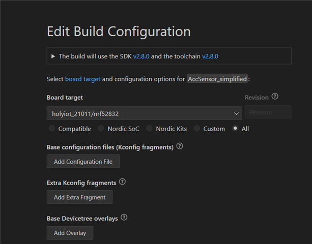
  • I'm using NCS version 2.8.0, with a custom board based on the nRF52832 (included in the boards directory) as the target, and incorporating the sensor and other modifications according to the schematic.

  • AccSensor_suggestion.zip

    Hello,

    Sorry for the late reply. I got something working on my end, but it was with a different sensor, so you need to modify it a bit. I made it just read the "WHO_AM_I" register, which on the mpu6050 is the 0x75 register address. I also added an .overlay file in your application folder, where I did some modifications. This will overwrite whatever is in the board files, so go through them and see if you want to revert something. For instance, I changed the LEDs to match the LED pins on the nRF52832 DK. 

    I also changed the I2C pins in the overlay file, so you can change it back from 24 to 5. I tested it now (after I zipped it), and it still works. 

    Best regards,

    Edvin

  • By the way, that solution is not optimal. I ended up with two devicetree instances in your tilt.c, because one was used to fetch the device i2c address, while the other was used to initialize it. I recommend that you check out the devAcademy course: NCS Fundamentals, which has a lesson on I2C in NCS:

    Lesson 6 covers I2C:
    https://academy.nordicsemi.com/courses/nrf-connect-sdk-fundamentals/lessons/lesson-6-serial-com-i2c/topic/exercise-1-6-2/

    Best regards,

    Edvin

  • Thanks for your help.

    Finally, it was necessary to connect to the I2C lines to observe what was really happening (it seemed impossible). I was greatly surprised when I tried using the official sensor driver again (just as I had initially attempted) and saw that it worked perfectly fine. I confirmed this both with the logic analyzer and through the RTT logs.

    However, when disconnecting the analyzer (from the computer, i.e., its power supply, not the probes from the I2C lines), the microcontroller was once again unable to communicate with the sensor. Yet, it still worked when testing communication from the I2C shell.

    This brings me back to my initial question. It seems clear that there is a hardware issue (which I did not design and cannot modify), but the communication works with the shell and not with the sensor driver. So, I don’t understand this inconsistency.

Reply
  • Thanks for your help.

    Finally, it was necessary to connect to the I2C lines to observe what was really happening (it seemed impossible). I was greatly surprised when I tried using the official sensor driver again (just as I had initially attempted) and saw that it worked perfectly fine. I confirmed this both with the logic analyzer and through the RTT logs.

    However, when disconnecting the analyzer (from the computer, i.e., its power supply, not the probes from the I2C lines), the microcontroller was once again unable to communicate with the sensor. Yet, it still worked when testing communication from the I2C shell.

    This brings me back to my initial question. It seems clear that there is a hardware issue (which I did not design and cannot modify), but the communication works with the shell and not with the sensor driver. So, I don’t understand this inconsistency.

Children
  • So you didn't get it working with the sample that I sent? 

    What analyzer did you use? Does it power the chip? Or is it only the thin cables shown in the picture (purple and orange) for SDA and SCL?

    So it doesn't work when you have the RTT log connected but the analyzer disconnected?

    What comes to mind is that perhaps your analyzer adds some pull configuration. Do you have the pull-up configuration on i2c1_default?

    	i2c1_default: i2c1_default {
    		group1 {
    			psels = <NRF_PSEL(TWIM_SDA, 0, 2)>,
    							<NRF_PSEL(TWIM_SCL, 0, 24)>;
    							bias-pull-up;
    		};
    	};
    	
    	i2c1_sleep: i2c1_sleep {
    		group1 {
    			psels = <NRF_PSEL(TWIM_SDA, 0, 2)>,
    							<NRF_PSEL(TWIM_SCL, 0, 24)>;
    							low-power-enable;
    		};
    	};

Related