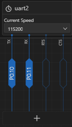
Testing RXD and TXD Connections

Is there a way to test that the RXD and TXD pins are sending and receiving data on the nrf5340? I am trying to connect these pins to the u-blox ANT-B10-00C using male to female jumper cables but when I try this setup, my serial terminal is not outputting any data.

Parents Reply Children
  • Hi

    Could you upload the overlay? I think I would also recommend to change the pins. If you look at the backside of the DK you can see the pins that is being used to the IMCU, LEDs, GPIO and crystals. I would suggest to not use the pins to the IMCU. It is possible to use them but then you need to disconnect the IMCU. I'm also wondering if you had any equipment to see if there is anything on the pins. If you don't have it no worries, its just easier while debugging to see if there is something there. 

    Just to verify, have you tried to connect to the ANT-B10-OOC with the use over a usb-serial converter? 

    Regards

    Runar

  • &uart2 {
        compatible = "nordic,nrf-uarte";
        current-speed = <115200>;
        status = "okay";
        pinctrl-0 = <&uart2_pins>;
        pinctrl-names = "default";
    };
    
    &pinctrl {
        uart2_pins: uart2_pins {
            group1 {
                psels = <NRF_PSEL(UART_TX, 0, 5)>,
                        <NRF_PSEL(UART_RX, 0, 6)>;
            };
        };
    };

    Here is the overlay. And I have changed it to pins 5 and 6 instead of 10 and 11. I have not tried to connect to the ANT-B10-00C using a usb-serial converter; I have been using a dual-row, 1.27 mm pitch, 20-pin, female adapter and male-female jumper wires. And this is what my terminal is currently outputting:

    uart:~$ *** Booting nRF Connect SDK v2.9.0-7787b2649840 ***
    *** Using Zephyr OS v3.7.99-1f8f3dc29142 ***
    UART2 communication test started...
    Sent: Hello ANT-B10!
    
    uart:~$ Received from ANReceived from ANT-B10: Huart:~$ Sent: Hello ANT-B10!
    Received from ANSent: Hello ANT-B10!
    Received from ANT-B10: euart:~$ Sent: Hello ANT-B10!
    Received from ANSent: Hello ANT-B10!
    Received from ANT-B10: luart:~$ Sent: Hello ANT-B10!
    Received from ANSent: Hello ANT-B10!
    Received from ANT-B10: luart:~$ Sent: Hello ANT-B10!
    Received from ANSent: Hello ANT-B10!
    Received from ANT-B10: ouart:~$ Sent: Hello ANT-B10!
    Received from ANSent: Hello ANT-B10!
    Received from ANT-B10:  uart:~$ Sent: Hello ANT-B10!
    Received from ANSent: Hello ANT-B10!
    Received from ANT-B10: Auart:~$ Sent: Hello ANT-B10!
    No response yet...
    Sent: Hello ANT-B10!
    No response yet...
    uart:~$ Sent: Hello ANT-B10!
    No response yet...
    Sent: Hello ANT-B10!
    No response yet...
    uart:~$ Sent: Hello ANT-B10!
    No response yet...
    Sent: Hello ANT-B10!
    No response yet...

    Do i need to set up RTS and CTS as well or just the RX and TX pins?

  • The overlay looks fine, 

    If you need RTS and CTS should be defined the documentation form Ublox.

    If flow control is not used, the UART_CTS pin is internally pulled down. However, it is good practice to connect UART_CTS to GND. Configure the UART connection not to use flow control using the command AT+UMRS=,0. Other necessary pins: • GND ground connection (pin 15 or 17) • +3V3 power supply (pin 2) • SWITCH_2 forces the board into the software update (boot loader) mode when driven low during board reset. • SWITCH_1 resets the board to its default settings when driven and then held low for at least 5 seconds – or until the +STARTUP event is received over the UART.

    From the AT command manual it looks like the module expect messages as defined here

    Regards

    Runar

Related