
Hi,
I am using a custom nRF52832 board with multiple ADC channel readings sequentially. I am trying to read thermistor (NTC) value on channel 7 and not getting accurate reading. As soon as I plug the thermistor, the value goes on decreasing/ stabilizing which goes below the actual/ anticipated reading that could be due to hardware/ software issue in my setup.
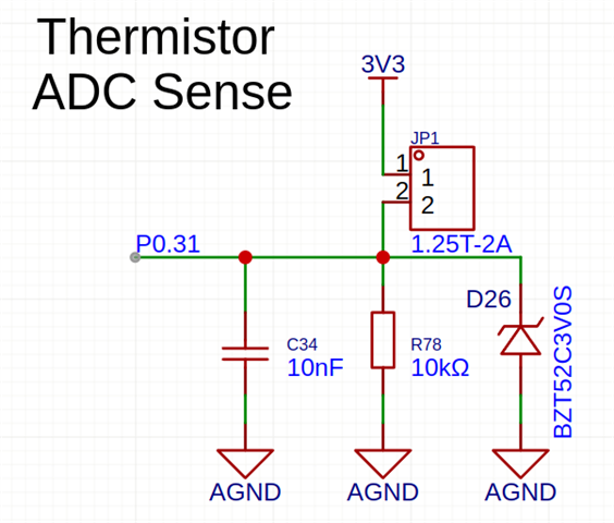
The schematic of that specific channel is:
The DTS for that specific channel is:
	// Thermistor
	channel@7 {
		reg = <7>;
		zephyr,gain = "ADC_GAIN_1_5";
		zephyr,reference = "ADC_REF_INTERNAL";
		zephyr,acquisition-time = <ADC_ACQ_TIME_DEFAULT>;
		zephyr,input-positive = <NRF_SAADC_AIN7>;
		zephyr,resolution = <10>;
		zephyr,oversampling = <8>;
	};
This is the output of channel 7 readouts after 1 sec interval:
ADC reading of device adc@40007000, channel 7: 555 = 1625 mV
ADC Thread fired!

ADC reading of device adc@40007000, channel 7: 545 = 1596 mV
ADC Thread fired!

ADC reading of device adc@40007000, channel 7: 538 = 1576 mV
ADC Thread fired!

ADC reading of device adc@40007000, channel 7: 533 = 1561 mV
ADC Thread fired!

ADC reading of device adc@40007000, channel 7: 527 = 1543 mV
ADC Thread fired!

ADC reading of device adc@40007000, channel 7: 523 = 1532 mV
ADC Thread fired!

ADC reading of device adc@40007000, channel 7: 513 = 1502 mV
ADC Thread fired!

ADC reading of device adc@40007000, channel 7: 510 = 1494 mV
ADC Thread fired!

ADC reading of device adc@40007000, channel 7: 509 = 1491 mV
ADC Thread fired!

ADC reading of device adc@40007000, channel 7: 511 = 1497 mV
ADC Thread fired!

ADC reading of device adc@40007000, channel 7: 504 = 1476 mV
ADC Thread fired!

ADC reading of device adc@40007000, channel 7: 504 = 1476 mV
ADC Thread fired!

ADC reading of device adc@40007000, channel 7: 501 = 1467 mV
ADC Thread fired!

ADC reading of device adc@40007000, channel 7: 505 = 1479 mV
The ADC reading falls/ stabilizes from 555 to 505 and I expect a value around 540 (measuring thermistor from meter then converting to raw adc value).
I have tried setting VDD and different ACQ times but didn't help.
Please suggest a solution.
Regards

