UARTE21 and SPIM20 on P2 issues

Hello and thank you for your time,

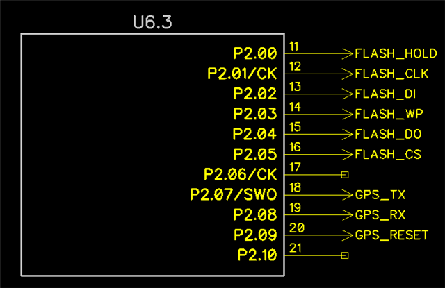
We have created a board using the nRF54l15 and have used P2.07 & P2.08 for UARTE21 and P2.00 to P2.05 for SPIM20.

UARTE21 and SPIM20 do not work on P2 thus far.

I have used UARTE00 and SPIM00, separately due to resource sharing issues, and both work with their separate devices, notably altering the current-speed to 1/8 normal.

The pin selection on P2 is dedicated and this is accounted for and shown to be correct on our board due to the UARTE00 and SPIM00 working with the devices.

The data sheets for the nRF54l15 "SEEM" to indicate that UART20/21 and SPIM20/21 can be used on P2, cross power domain, but I have not been able to get this to work properly and have found no examples showing this working.

So the questions are:

- do UART20/21 and SPIM20/21 work on P2 as indicated in the data sheet?

- are the rates normal for UART20/21 and SPIM20/21 on P2 or are they also multiplied by 8?

- if they do work, is their a working example for the nRF54l15DK?

- alternately, is there resource sharing such that UARTE00 and SPIM00 can be switched between each other at runtime?

During my search for answers I found one promising reference for this:

Case ID: 342324

Parents
  • Hi,

    I have used UARTE00 and SPIM00, separately due to resource sharing issues, and both work with their separate devices, notably altering the current-speed to 1/8 normal.

    There is a pull request to fix this (at least for UARTE00): https://github.com/zephyrproject-rtos/zephyr/pull/82112/

    - do UART20/21 and SPIM20/21 work on P2 as indicated in the data sheet?

    Yes, but you can only use the dedicated pins specified in pin assignment table (e.g. P2.07 for UARTE21 RX, P2.08 for UARTE21 TX). Also note that you need to enable Constant Latency mode when using pins on P2. This can be done as mentioned in the ticket you linked, or to force it on at all times, you can set CONFIG_SOC_NRF_FORCE_CONSTLAT=y in your prj.conf file.

    - are the rates normal for UART20/21 and SPIM20/21 on P2 or are they also multiplied by 8?

    The rates are normal. The clock source is related to the instance itself and not which pins you have connected the peripheral to.

    - if they do work, is their a working example for the nRF54l15DK?

    Attaching a modified version of the hello_world sample where UARTE21 is configured to use P2.08/P2.07:

    hello_world_nrf54l15_uart21_p2_ncs290.zip

    - alternately, is there resource sharing such that UARTE00 and SPIM00 can be switched between each other at runtime?

    Not a specific example for nRF54L15, but you can reference this sample that shows how to switch during runtime. Note that this is using NRFX and not the Zephyr drivers.

    Best regards,
    Jørgen

  • Hi,

    There should not be any conflicts with other parts of the chip by enabling Constant latency. However, enabling it will increase current consumption as more parts of the chip will be keep on all the time.

    1. Are you testing this on a nRF54L15 DK or on a custom board?
      1. If testing on a DK, which version of the DK are you using?
      2. If testing on a custom board, what is the marking on the chip you tested this on?
    2. Which nRF Connect SDK version did you use to build your application?
    3. Did you try out the sample I provided? This also sets the CONFIG_SOC_NRF_FORCE_CONSTLAT Kconfig. Did this sample work?
    4. Did you try to enable constant latency mode directly in the code, as suggested in the other ticket?

    Best regards,
    Jørgen

  • Thank you for the response, sorry for the late reply

    I have been working through this to try and figure out what the tripping point is and it seems to be a difference in the secure vs non-secure builds.

    Through a lot of trial and error I was able to prove this out.

    Your code, whose crux is adding: 

    CONFIG_SOC_NRF_FORCE_CONSTLAT=y
    in order to utilize cross-power 20/21 on P2
    This code works in the secure code, aka, no Trustzone code. It fails when used in a non-secure(ns) build.
    perhaps there is setting that needs to be adjusted that I am missing?
    This is easy to recreate with your code, simply unzip your base, and create a secure and non-secure build, you will have to add the overlay for the ns build, and then test each build.
    I hope there is a fix or setting that resolves this.
    This occurs on the nRF54l15DK ENGB chipset
    Thanks
    PS
    I would like to add this issue as well as it is associated with the NS build version:
    what exactly does this mean "UICR is hardware fixed to Secure"
    #ifdef USE_NON_SECURE_ADDRESS_MAP
            /* intentionally empty because UICR is hardware fixed to Secure */
    #else
            uicr: uicr@ffd000 {
                compatible = "nordic,nrf-uicr";
                reg = <0xffd000 0x1000>;
            };
    #endif
    Is the uicr some how locked to the ns build in use with TFM? this doesn't make sense to me. Perhaps the NS build requires the dts board files to manage this directly?
    I am wanting to use the NFC pins in GPIO mode
    &uicr {
        nfct-pins-as-gpios;
    };
    Thanks in advance
Reply
  • Thank you for the response, sorry for the late reply

    I have been working through this to try and figure out what the tripping point is and it seems to be a difference in the secure vs non-secure builds.

    Through a lot of trial and error I was able to prove this out.

    Your code, whose crux is adding: 

    CONFIG_SOC_NRF_FORCE_CONSTLAT=y
    in order to utilize cross-power 20/21 on P2
    This code works in the secure code, aka, no Trustzone code. It fails when used in a non-secure(ns) build.
    perhaps there is setting that needs to be adjusted that I am missing?
    This is easy to recreate with your code, simply unzip your base, and create a secure and non-secure build, you will have to add the overlay for the ns build, and then test each build.
    I hope there is a fix or setting that resolves this.
    This occurs on the nRF54l15DK ENGB chipset
    Thanks
    PS
    I would like to add this issue as well as it is associated with the NS build version:
    what exactly does this mean "UICR is hardware fixed to Secure"
    #ifdef USE_NON_SECURE_ADDRESS_MAP
            /* intentionally empty because UICR is hardware fixed to Secure */
    #else
            uicr: uicr@ffd000 {
                compatible = "nordic,nrf-uicr";
                reg = <0xffd000 0x1000>;
            };
    #endif
    Is the uicr some how locked to the ns build in use with TFM? this doesn't make sense to me. Perhaps the NS build requires the dts board files to manage this directly?
    I am wanting to use the NFC pins in GPIO mode
    &uicr {
        nfct-pins-as-gpios;
    };
    Thanks in advance
Children
No Data
Related