nRF54L15: UART pinout not working unless connecting the RTT viewer

Hi everyone,

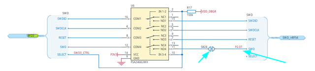
I am working with the new nRF54L15 and have connected UART21 to pins 2.07-2.08, which are capable of handling both Trace data and UARTE. However, I am encountering an unusual behavior with the UART RXD pin.

When I attempt to use the UART RXD pin, it only works fine when either:

  • The JLINK is connected via SWD
  • The RTT Viewer is connected

If neither of the above tools are connected, I am unable to use the UART RXD at all.

Has anyone else experienced a similar issue with the nRF54L15? Any ideas on what might be causing this behavior or suggestions on how to resolve it would be greatly appreciated.

Thank you in advance for your help!


Parents Reply Children
  • Hi ,

    Thank you for your answer, but I am not using the DK. I am using my prototype, without anything connected there.

    The behavior is, if I connect to the board using JLinkExe => connect command the RX is available otherwise it doesn't work. I am testing with echo_bot sample. 

    Also, if I use the config CONFIG_NRF_APPROTECT_LOCK=y I am not able to connect JLink and the RX never works. It seems that something happens when I connect JLink that allows the RX to receive data.

    Any thoughts? 

  • Also found this:


    And I am trying to understand "For nRF54L devices, firmware must open the debugger signals in Tamper Controller." but the link in the page is not working: https://docs.nordicsemi.com/bundle/ncs-latest/page/nrf/security/ap_protect.html


  •  the only way to make this work seems to 
    be enabling the debug domain by setting this register to 1:


    If I read the value at startup and it shows or it's set to 0:

    • P2.07 UART RX only works while a JLink Debug session is open. Once the debug session is closed, RX stops functioning.

    If I set the pin value to 1:

    • P2.07 UART RX works consistently, and I can still open and close a JLink Debug session without issues.

    It seems that “acquiring” the GPIO makes the UART21 RX in P2.07 work, but “releasing” it or having it in the default state causes it to fail. Could you help me understand why this might be happening? Is it the intended behaviour?

    Additionally, in a separate ticket my teammate is preparing, we will submit a schematic to Nordic for review. This schematic places P2.07 as the RX pin for a UART to be used in inline production tests (and will remain so in mass production). Given the issue in this ticket, I am not comfortable keeping P2.07 as the RX of the UART. Could you please advise and give feedback based on my observations?

    Thank you in advance!

Related