Custom board based on nrf5340 CLAA not working after flashing the application

Hi,

I designed a custom PCB with the nrf5340 CLAA chip and am testing out the board. I want to flash a simple project of lighting up the on-board LED (the LED is connected to P1.07 in my board design). In nrf connect SDK in VS Code, I was able to create a custom board for nrf5340 QKAA (I was told this is fine for CLAA too), add the GPIO pin P1.07 in the DeviceTree, build the project without errors and flash the code to my board via JLink successfully. However, the LED is not lighted up. When I tried to debug, the process always stops at the step “Starting target CPU…” and won’t let me proceed.

I also tried to control the LED directly using JLink.exe via command line (I am using a windows machine because I encountered more issues on mac). I could connect to the chip in JLink. However, I was not able to write the values directly to the registers to light up the LED either. I wrote the values but when I checked the memory at the address, it was still 0. I checked the soldering of my board physically and they are all connected. I measured RESET and Power and they are both around 3.3V. Is there anything that you think I should try to solve this issue? Is there anything specific I should do to flash the code for the first time? (E.g. the chip is initially locked/protected so we can’t write to its memory directly for the first time?) Any advice would be appreciated. Thanks!

Parents
  • Hi

    Does your custom board have a 32MHz crystal onboard? If not, that might be why you're only able to see it when a debugger is connected, as in that case the custom board may source the 32MHz crystal from the DK.

    If you do have the 32MHz crystal on your custom board, please double check that it is mounted correctly on the custom board, as a common mistake is that it is mounted 45 degrees off.

    Best regards,

    Simon

  • Hi Simon,

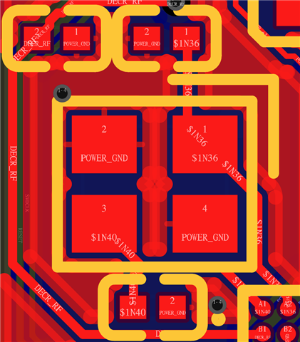
    I was able to get the board working also after flashing. I do have a 32 MHz crystal (Seiko Epson Q22FA12800025) on board and it is connected to the nrf5340 chip as shown in the figure below. Can you help me check this is correct?

    Also, I am trying to test my I2S interface but found out that the SCK and LRCLK is not stable. Is there a place I need to configure to use this external 32 MHz crystal as the main clock to provide stable clock signals? Thanks!

    Best,

    Ke

Reply
  • Hi Simon,

    I was able to get the board working also after flashing. I do have a 32 MHz crystal (Seiko Epson Q22FA12800025) on board and it is connected to the nrf5340 chip as shown in the figure below. Can you help me check this is correct?

    Also, I am trying to test my I2S interface but found out that the SCK and LRCLK is not stable. Is there a place I need to configure to use this external 32 MHz crystal as the main clock to provide stable clock signals? Thanks!

    Best,

    Ke

Children
No Data
Related