CST816S input driver i2c failed to read

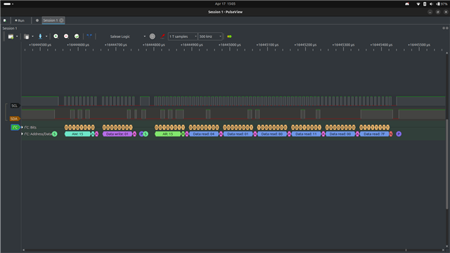
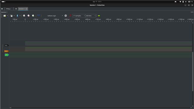
I have problem with i2c that can't read the cst816s, its always return log message `<err> cst816s: failed reading chip id` and `<err> cst816s: Could not read x data` when touched. i'm using the nRF52832. is there any configuration i need to do?

the board device tree: 

/dts-v1/;
#include <nordic/nrf52832_qfaa.dtsi>

...

&flash0 {
	partitions {
		compatible = "fixed-partitions";
		#address-cells = <1>;
		#size-cells = <1>;

		boot_partition: partition@0 {
			label = "mcuboot";
			reg = <0x00000000 DT_SIZE_K(48)>;
		};

		slot0_partition: partition@c000 {
			label = "image-0";
			reg = <0x0000c000 DT_SIZE_K(220)>;
		};

		slot1_partition: partition@43000 {
			label = "image-1";
			reg = <0x00043000 DT_SIZE_K(220)>;
		};

		storage_partition: partition@7a000 {
			label = "storage";
			reg = <0x0007a000 DT_SIZE_K(24)>;
		};
	};
};
&gpio0 {
	status = "okay";
};

&gpiote {
	status = "okay";
};

&rtc2 {
	status = "okay";
};

&uart0 {
	status = "okay";
	pinctrl-0 = <&uart0_default>;
	pinctrl-1 = <&uart0_sleep>;
	pinctrl-names = "default", "sleep";
	current-speed = <115200>;
};

&i2c1 {
	status = "okay";
	pinctrl-0 = <&i2c1_default>;
	pinctrl-1 = <&i2c1_sleep>;
	pinctrl-names = "default", "sleep";
};

the pinctrl file:

&pinctrl {
	uart0_default: uart0_default {
		group1 {
			psels = <NRF_PSEL(UART_TX, 0, 24)>, <NRF_PSEL(UART_RX, 0, 23)>;
		};
	};

	uart0_sleep: uart0_sleep {
		group1 {
			psels = <NRF_PSEL(UART_TX, 0, 24)>, <NRF_PSEL(UART_RX, 0, 23)>;
			low-power-enable;
		};
	};

	spi0_default: spi0_default {
		group1 {
			psels = <NRF_PSEL(SPIM_MOSI, 0, 29)>, <NRF_PSEL(SPIM_SCK, 0, 28)>;
		};
	};

	spi0_sleep: spi0_sleep {
		group1 {
			psels = <NRF_PSEL(SPIM_MOSI, 0, 29)>, <NRF_PSEL(SPIM_SCK, 0, 28)>;
			low-power-enable;
		};
	};

	i2c1_sleep: i2c1_sleep {
		group1 {
			psels = <NRF_PSEL(TWIM_SDA, 0, 9)>, <NRF_PSEL(TWIM_SCL, 0, 10)>;
			low-power-enable;
		};
	};

	i2c1_default: i2c1_default {
		group1 {
			psels = <NRF_PSEL(TWIM_SDA, 0, 9)>, <NRF_PSEL(TWIM_SCL, 0, 10)>;
		};
	};
};

the overlay file:

/ {
    chosen {
        zephyr,display = &display;
        zephyr,keyboard-scan = &touch_screen;
    };

    aliases {
        input = &touch_screen;
    };

    leds {
        compatible = "gpio-leds";
        lcd_backlight: lcd_backlight {
            gpios = <&gpio0 11 GPIO_ACTIVE_LOW>;
            label = "LCD Backlight";
        };
    };

    lvgl_pointer_input:lvgl_pointer {
        compatible = "zephyr,lvgl-pointer-input";
        input = <&touch_screen>;
    };
};

&spi0 {
    compatible = "nordic,nrf-spim";
	status = "okay";
	pinctrl-0 = <&spi0_default>;
	pinctrl-1 = <&spi0_sleep>;
	pinctrl-names = "default", "sleep";
	cs-gpios = <&gpio0 30 GPIO_ACTIVE_LOW>;

	display: st7789v@0 {
        label = "ST7789 Display";
		compatible = "sitronix,st7789v";
        spi-max-frequency = <20000000>;
        reg = <0>;
        cmd-data-gpios = < &gpio0 27 GPIO_ACTIVE_LOW>;
        reset-gpios = < &gpio0 31 GPIO_ACTIVE_LOW>;
        width = <240>;
        height = <240>;
        x-offset = <0>;
        y-offset = <0>;
        vcom = <0x19>;
        gctrl = <0x35>;
        vrhs = <0x12>;
        vdvs = <0x20>;
        mdac = <0x00>;
        gamma = <0x01>;
        colmod = <0x05>;
        lcm = <0x2c>;
        porch-param = [0c 0c 00 33 33];
        cmd2en-param = [5a 69 02 01];
        pwctrl1-param = [a4 a1];
        pvgam-param = [D0 04 0D 11 13 2B 3F 54 4C 18 0D 0B 1F 23];
        nvgam-param = [D0 04 0C 11 13 2C 3F 44 51 2F 1F 1F 20 23];
        ram-param = [00 F0];
        rgb-param = [CD 08 14];
	};
};

&i2c1 {
    clock-frequency = <I2C_BITRATE_FAST>;

    touch_screen: cst186s@15 {
        label = "CST816S Touch Screen";
        status = "okay";
        compatible = "hynitron,cst816s";
        reg = <0x15>;
        irq-gpios = <&gpio0 26 GPIO_ACTIVE_LOW>;
        rst-gpios = <&gpio0 21 GPIO_ACTIVE_LOW>;
    };
};

Parents
  • Hi,

    Are you able to get logic analyzer or oscilloscope readings from the I2C?

    Regards,
    Sigurd Hellesvik

  • Hi, thanks for your response. As you can see, there is nothing on the i2c reading with zephyr. I have tried it with other frameworks and it still works fine. I'm still curious what makes i2c (with gpio sda 9 and gpio scl 10) not output any data, maybe I missed something when setting up the board devicetree or overlay.

    I2c readings with other framework:

    I2c readings with zephyr:

  • nanangcreacoll said:
    I try directly using I2C to initialize CST816S. I try to make my own device tree binding for CST816S. I still don't know which part I should fix, I2C still can't read the chip. RST and IRQ gpio work fine.

    Alright, then we have tried two different ways to read the CST816S over I2C.

    At this point, I think it would be a good idea to look at the hardware.

    How do you connect the CST to the nRF?
    Do you have another I2C device that you can try to read with the nRF, to verify that the I2C code work?

  • I use this board, connect the touch screen with the socket on the board.

    I have a PCF8574 GPIO Expander that I am using to try out I2C, it can read and write to the PCF8574.

    Main code with PCF8574:

    #include <zephyr/kernel.h>
    #include <zephyr/device.h>
    #include <zephyr/devicetree.h>
    #include <zephyr/drivers/i2c.h>
    
    #define LOG_LEVEL LOG_LEVEL_DBG
    #include <zephyr/logging/log.h>
    LOG_MODULE_REGISTER(app, LOG_LEVEL);
    
    #define PCF8574_NODE DT_NODELABEL(pcf8574)
    
    int main(void)
    {
            const struct i2c_dt_spec pcf8574 = I2C_DT_SPEC_GET(PCF8574_NODE);
            if (!i2c_is_ready_dt(&pcf8574))
            {
                    LOG_ERR("I2C device not ready");
                    return -ENODEV;
            }
    
            int ret;
            uint8_t data = 0;
            
            ret = i2c_read_dt(&pcf8574, &data, sizeof(data));
            if (ret < 0)
            {
                    LOG_ERR("Failed to read data: %d", ret);
                    return ret;
            }
            LOG_DBG("Initial data read: 0x%02X", data);
    
            while(1)
            {
                    uint8_t read_data;
                    
                    ret = i2c_write_read_dt(&pcf8574, &data, sizeof(data), &read_data, sizeof(read_data));
                    if (ret < 0)
                    {
                            LOG_ERR("Failed to write/read data: %d", ret);
                    }
                    LOG_DBG("Wrote data: 0x%02X, Read data: 0x%02X", data, read_data);
    
                    if (data == 0)
                    {
                            data = 1;
                    }
                    else if (data & 0x80)
                    {
                            data = 0;
                    }
                    else
                    {
                            data <<= 1;
                    }
                    
                    k_msleep(1000);
            }
            return 0;
    }

    Output log:

    ** Booting nRF Connect SDK v2.7.0-5cb85570ca43 ***
    *** Using Zephyr OS v3.6.99-100befc70c74 ***
    [00:00:00.391,174] <dbg> app: main: Initial data read: 0xFF
    [00:00:00.391,387] <dbg> app: main: Wrote data: 0xFF, Read data: 0xFF
    [00:00:01.391,632] <dbg> app: main: Wrote data: 0x00, Read data: 0x00
    [00:00:02.391,967] <dbg> app: main: Wrote data: 0x01, Read data: 0x01
    [00:00:03.392,303] <dbg> app: main: Wrote data: 0x02, Read data: 0x02
    [00:00:04.392,639] <dbg> app: main: Wrote data: 0x04, Read data: 0x04
    [00:00:05.392,974] <dbg> app: main: Wrote data: 0x08, Read data: 0x08
    [00:00:06.393,310] <dbg> app: main: Wrote data: 0x10, Read data: 0x10
    [00:00:07.393,646] <dbg> app: main: Wrote data: 0x20, Read data: 0x20
    [00:00:08.393,981] <dbg> app: main: Wrote data: 0x40, Read data: 0x40
    [00:00:09.394,317] <dbg> app: main: Wrote data: 0x80, Read data: 0x80

    Is there a possible problem with the board? I've used it with other platforms and it works fine.

  • When I tried with PCF8574, I actually tried it first with another platform to read and write to PCF8574 (it can read and write), then back to zephyr and it works. If I try directly with zephyr, it can't read and write to PCF8574.

  • Let me try to summarize this ticket, to get an overview. Could you go over and then correct me anywhere I am wrong? I put a question mark after the ones I am unsure of.
    You have tested two different sensors over I2C, and here are the results:

    EDITED: based on later answers.

    CST816S

    SDK version: v2.7.0

    Test 1:
    Board: nRF52 custom board
    Sensor location: Wired LCD connected to nRF52 custom board
    Software: Zephyr code
    Result: Nothing on I2C lines

    Test 2:
    Board: nRF52 custom board?
    Sensor location: Wired LCD connected to nRF52 custom board
    Software: third party code
    Result: I2C works

    PCF8574

    SDK version: v2.7.0

    Test 3:
    Board: nRF52 custom board
    Sensor location: External board
    Software: third party code
    Result: I2C works

    Test 4:
    Board: nRF52 custom board
    Sensor location: External board
    Software: Zephyr code
    Result: Nothing on I2C lines
    Comment: Will work if done right after Test 3

  • In test 1 and test 2, the sensor location is on LCD display which is connected by wire via a socket to nRF custom board. In test 3, it uses the nRF custom board, but the software was in another framework. In test 4, yes, it will work if done right after test 3.

Reply Children
  • Thanks for the clarifications, I edited them into the summary.

    Let us focus on Test 1 for now. Can you try to use the blinky sample to "blink" on the pins that you use for the LCD display? This is a good way to see if you can control those pins at all from the MCU.

  • I have tried the blinky sample for the SCL and SDA pins (GPIO 9 and 10) and it works. As for other pins for LCD display such as SPI, backlight, and Interrupt, all work fine. It can run the display and provide log message output for interrupts.

    blinky sample code:

    /*
     * Copyright (c) 2016 Intel Corporation
     *
     * SPDX-License-Identifier: Apache-2.0
     */
    
    #include <stdio.h>
    #include <zephyr/kernel.h>
    #include <zephyr/drivers/gpio.h>
    
    /* 1000 msec = 1 sec */
    #define SLEEP_TIME_MS   1000
    
    /* The devicetree node identifier for the "led0" alias. */
    #define LED0_NODE DT_ALIAS(led0)
    #define LED1_NODE DT_ALIAS(led1)
    
    /*
     * A build error on this line means your board is unsupported.
     * See the sample documentation for information on how to fix this.
     */
    static const struct gpio_dt_spec led0 = GPIO_DT_SPEC_GET(LED0_NODE, gpios);
    static const struct gpio_dt_spec led1 = GPIO_DT_SPEC_GET(LED1_NODE, gpios);
    
    int main(void)
    {
    	int ret;
    	bool led_state = true;
    
    	if (!gpio_is_ready_dt(&led0)) {
    		return 0;
    	}
    	if (!gpio_is_ready_dt(&led1)) {
    		return 0;
    	}
    
    	ret = gpio_pin_configure_dt(&led0, GPIO_OUTPUT_ACTIVE);
    	if (ret < 0) {
    		return 0;
    	}
    	ret = gpio_pin_configure_dt(&led1, GPIO_OUTPUT_ACTIVE);
    	if (ret < 0) {
    		return 0;
    	}
    
    	while (1) {
    		ret = gpio_pin_toggle_dt(&led0);
    		if (ret < 0) {
    			return 0;
    		}
    		ret = gpio_pin_toggle_dt(&led1);
    		if (ret < 0) {
    			return 0;
    		}
    
    		led_state = !led_state;
    		printf("LED state: %s\n", led_state ? "ON" : "OFF");
    		k_msleep(SLEEP_TIME_MS);
    	}
    	return 0;
    }


    overlay file:
    / {
        aliases {
            led0 = &led0;
            led1 = &led1;
        };
    
        leds {
            compatible = "gpio-leds";
            led0: led0 {
                label = "LED0";
                gpios = <&gpio0 9 GPIO_ACTIVE_LOW>;
            };
            led1: led1 {
                label = "LED1";
                gpios = <&gpio0 10 GPIO_ACTIVE_LOW>;
            };
        };
    };

  • Hm, if the pins works but I2C does not do anything, I am getting out of ideas here.

    From your trace below, you get nothing on I2C. That is odd, as the nRF should send something.
    Perhaps it is just going to fast, and the oscilloscope does not pick up the signal if it is not repeated?

    Can you try to look at the I2C lines again, and then make them log for a longer time. Then reset the device multople times, and see if you can see some initial I2C communication. Do you still see nothing?

Related