custom nRF5340 board no bluetooth signal

Hi Community,

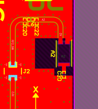
I designed a similar board asThingy53, espacially the antenna parts are almost the same, except the RF switch, we replace it with another one (BGS12WN6E6327XTSA1), then we found there is some issue to make the switch work properly, so I just removed the RF switch and short the RF output to the short range antenna, which means, now only one anntenna is connected to the RF, even so, I cannot see any RF signal on the mobile phone. 

but the output from UART seems no problem:

*** Booting nRF Connect SDK v3.5.99-ncs1 ***
[00:00:00.303,100] <inf> Custom_board: Starting Custom_board...

[00:00:00.309,020] <inf> fs_nvs: 8 Sectors of 4096 bytes
[00:00:00.309,020] <inf> fs_nvs: alloc wra: 0, fd0
[00:00:00.309,051] <inf> fs_nvs: data wra: 0, 1c
[00:00:00.334,167] <inf> bt_hci_core: HW Platform: Nordic Semiconductor (0x0002)
[00:00:00.334,197] <inf> bt_hci_core: HW Variant: nRF53x (0x0003)
[00:00:00.334,228] <inf> bt_hci_core: Firmware: Standard Bluetooth controller (0x00) Version 54.58864 Build 1214809870
[00:00:00.336,456] <inf> bt_hci_core: No ID address. App must call settings_load()
[00:00:00.338,897] <inf> bt_hci_core: Identity: E6:BD:87:6D:09:49 (random)
[00:00:00.338,928] <inf> bt_hci_core: HCI: version 5.4 (0x0d) revision 0x218f, manufacturer 0x0059
[00:00:00.338,928] <inf> bt_hci_core: LMP: version 5.4 (0x0d) subver 0x218f
[00:00:00.342,742] <inf> Custom_board: Bluetooth initialized

[00:00:00.348,327] <inf> Custom_board: Advertising successfully started

the same code, if I compiled it for the nRF5340DK, the bluetooth signal can be observed. 

So I just curious if I did something wrong in my board files or something else? 

I have been strugled in this issue for a long time, please help me with it, thanks a lot!

Best regards

Danny

Parents
  • Have you hade the design fully reviewed by us? 


    My guess is that there is an issue with the antenna or RF path in some way and that this impacts the range, so maybe you need to be very close, try a few centimeters. And only have the PCB, if there is any casing or other material in the way or enclosing the antenna\PCB this might be a reason to why the RF is bad. 


    Alternatively it might be the the clock, the 32MHz might be off and that can contribute to the issue. Make sure it is loaded correctly. 

    Regards,
    Jonathan

  • Hi   

    1. it's not reviewed by you. I just checked the Thingy53 PCB file, found the followed differences:

    Thingy53 PCB:

    trace width: 0.6mm

    grounded vias around the clear area of antenna .

    My PCB:

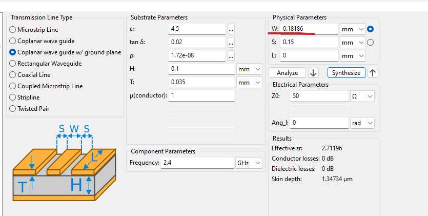
    trace width: 0.18mm:

    I used this calculation, therefore I used 0.18mm RF trace width, is there anything wrong?

    forgot to put grounded vias around the clear area of antenna.

    I even put the PCB very close to the mobile phone, still can not see any siganl from my PCB.

    2. I think I checked the 32M Hz crystal before, it's running, and all the other peripherals are running correctly, I2C, SPI, PWM...


    Best regards
    Danny

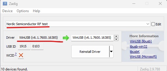
  • in my case, it's nRF5340DK, not dongle. I can only see two CDC devices.

    Yes, it's connected as I do the update and install.

  • danny0007 said:
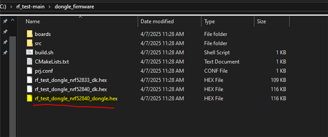
    I got a USB dongle with nRF52840, I flashed  the rf_test_dongle_nrf52840_dongle.hex file with nRF Connect Programmer. how to use it in this case?

    You said earlier you had a nRF52840 dongle? 


    The nRF5340DK is not supported as the "Dongle" unit here in this application. 

    " Only nRF52840DK and dongle have been tested."

    Regards,
    Jonathan

  • but my custom board is based on nRF5340.

    Even if it's working with nRF52840 dongle, how can this rf_test code help me with debugging the RF function of my nRF5340 custom board? 

    My thoughts is first to test the rf_test code with nRF5340DK, then move the code to my custom board.

    Begards

    Danny

  • Sorry for the ambiguity, 


    So the python application together with the nRF52840 dongle acts as the tools to enable testing on the custom board\DK of your choice. 


    So the python app + the dongle with the dongle firmware is part of the tools to enable testing. 

    The DK\custom board and the hex file with only the name of the device is the Device Under Testing(DUT), This unit only needs power to work after the firmware is flashed. 


    The python app + dongle activates the DUT mode of choice wirelessly over the radio. A power cycle of the DUT is needed to reset the device and make it except new commands. 

    Regards,
    Jonathan

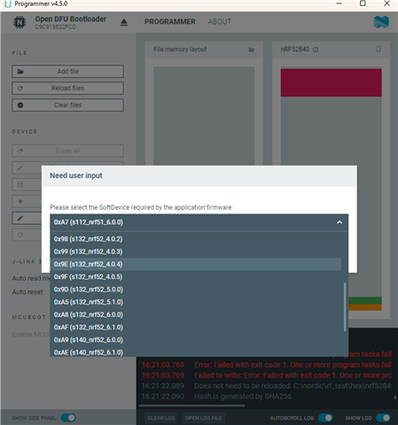
  • I'm trying to flash the nRF52840 dongle with nrf52840.hex via nRF connect.

    which softDevice shall I select? 

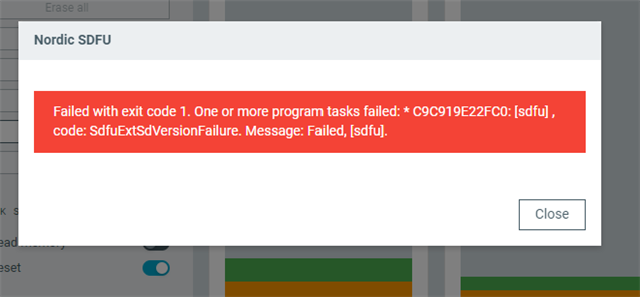
    I tried several, get this error:

    Regard

    Danny

Reply Children
No Data
Related