Dear Nordic,
I have a few questions I would like to ask.
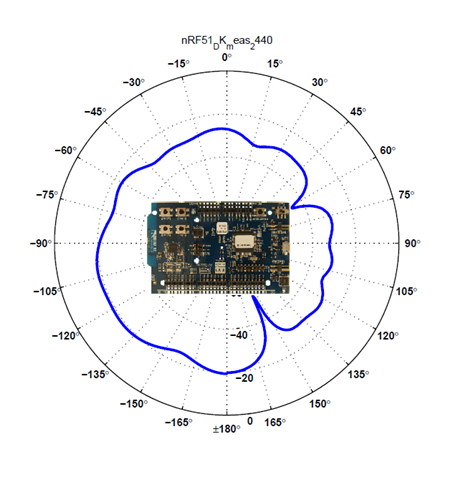
1. I would like to inquire if there is an antenna pattern for the nRF54L15DK PCB.
I have already searched through the related nRF54L15DK websites but could not find any relevant information.
2. Does the antenna pattern have an impact on the collected IQ data? Is there any relevant principle or explanation for this?
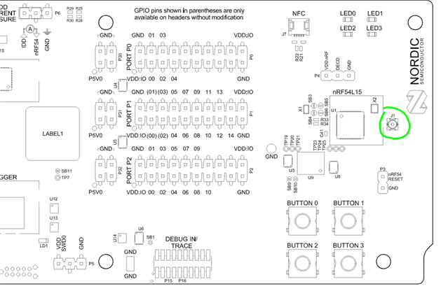
3.Currently, the nRF54L15DK only has a single PCB PIFA antenna. In my experiments, I observed that certain directions have a negative impact on the ranging performance.
I would like to understand if this is related to the antenna's strength. If so, how can this be improved?
Thank you!