
Hello everyone,
I am a EE student and this problem came up during my first big project in zephyr. I'm trying to connect a pwm peripheral (pwm1) to the timer 2 hardware timer in zephyr. The idea is to have the timer in the counter mode and have it increment every rising edge of the pwm signal generated by the pwm0 peripheral (on the peripheral itself, I'm using all 4 channels and I'm generating identical signals on all 4 - 102.4 kHz pwm that serves as a clock input to a different sensor component). After 15360 cycles of pwm signal, the timer is supposed to fire and execute a callback function.
In this code (it's just some testing code) I also try to toggle a led every time the timer time passes. I tried using nrf_ppi.h but it didn't work since in the lines:
nrf_ppi_channel_endpoint_setup();
nrf_ppi_channel_enable();
I would have to use to actually connect the peripherals via PPI I would have to use the following arguments:
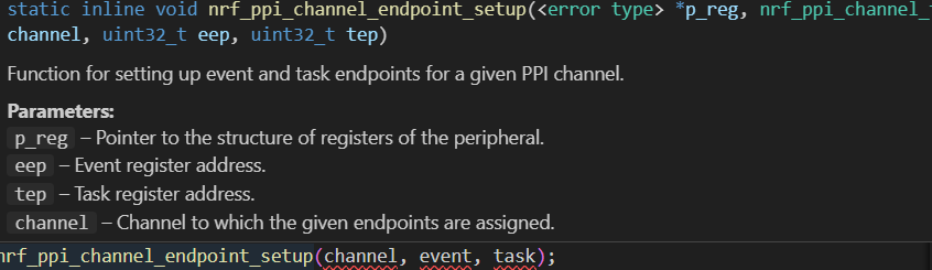
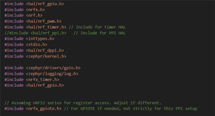
and in some online example (there is almost none) I found that for the *p_reg argument one is supposed to use NRF_PPI that is supposed to be defined in the library but for me it wasn't. Hence, I switched to dppi and it at least built. These are my includes:
these are my defines:
#define PIN_PWM0_CH0 29
#define PIN_PWM0_CH1 10
#define PIN_PWM0_CH2 8
#define PIN_PWM0_CH3 30

#define PIN_PWM1_CH0 11
#define PIN_PWM1_CH1 39
#define COUNTERTOPi 156
#define DUTY_CYCLE (COUNTERTOPi / 2)

#define LED_PIN 28  // P0.28 (confirm this for your board)
#define TIMER_INST_IDX 2

// --- PPI/Timer specific definitions ---
#define PWM_COUNT_THRESHOLD 15360 // Your desired count of PWM cycles
#define DPPI_CH 0
// Define the PPI channel to use (choose an unused one, 0-19 typically on nRF52)
#define PPI_CHANNEL_PWM_TO_TIMER 0
here's the callback function of the timer:
// Forward declaration for the interrupt handler
void timer2_irq_handler(void);

// Our custom callback function
void my_pwm_cycle_callback(void) {
    static bool led_state = false;
    led_state = !led_state;

    if (led_state) {
        nrf_gpio_pin_set(LED_PIN);
    } else {
        nrf_gpio_pin_clear(LED_PIN);
    }

    printf("PWM cycle count reached! LED toggled.\n");
}

// Timer 2 Interrupt Handler
void timer2_irq_handler(void) {
    printf("In timer 2 irq\n");
    if (NRF_TIMER2->EVENTS_COMPARE[0]) {
        NRF_TIMER2->EVENTS_COMPARE[0] = 0; // Clear the event
        printf("In if of timer 2 irq\n");
        // Call your custom callback
        my_pwm_cycle_callback();

        // Optionally, reset the timer to count again
        NRF_TIMER2->TASKS_CLEAR = 1;
        //NRF_TIMER2->TASKS_START = 1;
        // If you want to stop counting after one trigger, disable PPI:
        // nrf_ppi_channel_disable(PPI_CHANNEL_PWM_TO_TIMER);
    }
}
This is my main with the pwm bare metal generation first (this I probed and it is truly generated) followed by the timer2 setup and ppi connecting as well as some printing for debugging.
int main{
    nrf_gpio_cfg_output(LED_PIN);
    nrf_gpio_pin_clear(LED_PIN); // Start OFF
    // --- PWM Initialization (Your existing code) ---
    NRF_PWM1->ENABLE = 1;
    printf("PWM1 ENABLE: %" PRIu32 "\n", NRF_PWM1->ENABLE);
    static uint16_t pwm1_seq[2] = { DUTY_CYCLE, DUTY_CYCLE };
    static uint16_t pwm0_seq[4] = { DUTY_CYCLE, DUTY_CYCLE, DUTY_CYCLE, DUTY_CYCLE };

    NRF_PWM1->PSEL.OUT[0] = (PIN_PWM1_CH0 << PWM_PSEL_OUT_PIN_Pos) |
                            (PWM_PSEL_OUT_CONNECT_Connected << PWM_PSEL_OUT_CONNECT_Pos);
    printf("PWM1 PSEL.OUT[0] = %" PRIu32 "\n", NRF_PWM1->PSEL.OUT[0]);
    NRF_PWM1->PSEL.OUT[1] = (PIN_PWM1_CH1 << PWM_PSEL_OUT_PIN_Pos) |
                            (PWM_PSEL_OUT_CONNECT_Connected << PWM_PSEL_OUT_CONNECT_Pos);
    NRF_PWM1->PSEL.OUT[2] = 0xFFFFFFFF;
    NRF_PWM1->PSEL.OUT[3] = 0xFFFFFFFF;

    NRF_PWM0->PSEL.OUT[0] = (PIN_PWM0_CH0 << PWM_PSEL_OUT_PIN_Pos) |
                            (PWM_PSEL_OUT_CONNECT_Connected << PWM_PSEL_OUT_CONNECT_Pos);
    printf("PWM0 PSEL.OUT[0] = %" PRIu32 "\n", NRF_PWM0->PSEL.OUT[0]);
    NRF_PWM0->PSEL.OUT[1] = (PIN_PWM0_CH1 << PWM_PSEL_OUT_PIN_Pos) |
                            (PWM_PSEL_OUT_CONNECT_Connected << PWM_PSEL_OUT_CONNECT_Pos);
    NRF_PWM0->PSEL.OUT[2] = (PIN_PWM0_CH2 << PWM_PSEL_OUT_PIN_Pos) |
                            (PWM_PSEL_OUT_CONNECT_Connected << PWM_PSEL_OUT_CONNECT_Pos);
    NRF_PWM0->PSEL.OUT[3] = (PIN_PWM0_CH3 << PWM_PSEL_OUT_PIN_Pos) |
                            (PWM_PSEL_OUT_CONNECT_Connected << PWM_PSEL_OUT_CONNECT_Pos);

    NRF_PWM1->ENABLE = (PWM_ENABLE_ENABLE_Enabled << PWM_ENABLE_ENABLE_Pos);
    NRF_PWM1->MODE = (PWM_MODE_UPDOWN_Up << PWM_MODE_UPDOWN_Pos);
    NRF_PWM1->PRESCALER = (PWM_PRESCALER_PRESCALER_DIV_1 << PWM_PRESCALER_PRESCALER_Pos);
    NRF_PWM1->COUNTERTOP = (COUNTERTOPi << PWM_COUNTERTOP_COUNTERTOP_Pos);
    NRF_PWM1->LOOP = (0xFFFF << PWM_LOOP_CNT_Pos); // Loop forever, or for a very long time
    NRF_PWM1->SHORTS = PWM_SHORTS_LOOPSDONE_SEQSTART0_Enabled << PWM_SHORTS_LOOPSDONE_SEQSTART0_Pos;


    // NRF_PWM1->DECODER = (PWM_DECODER_LOAD_Common << PWM_DECODER_LOAD_Pos) |
    //                     (PWM_DECODER_MODE_RefreshCount << PWM_DECODER_MODE_Pos);
    NRF_PWM1->DECODER = (PWM_DECODER_LOAD_Common << PWM_DECODER_LOAD_Pos) |
                    (PWM_DECODER_MODE_NextStep << PWM_DECODER_MODE_Pos);


    NRF_PWM0->ENABLE = (PWM_ENABLE_ENABLE_Enabled << PWM_ENABLE_ENABLE_Pos);
    NRF_PWM0->MODE = (PWM_MODE_UPDOWN_Up << PWM_MODE_UPDOWN_Pos);
    NRF_PWM0->PRESCALER = (PWM_PRESCALER_PRESCALER_DIV_1 << PWM_PRESCALER_PRESCALER_Pos);
    NRF_PWM0->COUNTERTOP = (COUNTERTOPi << PWM_COUNTERTOP_COUNTERTOP_Pos);
    NRF_PWM0->LOOP = (0xFFFF << PWM_LOOP_CNT_Pos);

    NRF_PWM0->DECODER = (PWM_DECODER_LOAD_Common << PWM_DECODER_LOAD_Pos) |
                        (PWM_DECODER_MODE_RefreshCount << PWM_DECODER_MODE_Pos);

    NRF_PWM1->SEQ[0].PTR = 2;//((uint32_t)(pwm1_seq) << PWM_SEQ_PTR_PTR_Pos);
    NRF_PWM1->SEQ[0].CNT = (2 << PWM_SEQ_CNT_CNT_Pos);
    NRF_PWM1->SEQ[0].REFRESH = 0;
    NRF_PWM1->SEQ[0].ENDDELAY = 0;

    NRF_PWM0->SEQ[0].PTR = ((uint32_t)(pwm0_seq) << PWM_SEQ_PTR_PTR_Pos);
    NRF_PWM0->SEQ[0].CNT = (4 << PWM_SEQ_CNT_CNT_Pos);
    NRF_PWM0->SEQ[0].REFRESH = 0;
    NRF_PWM0->SEQ[0].ENDDELAY = 0;

    // --- Timer 2 Initialization for Counting ---
    NRF_TIMER2->MODE = NRF_TIMER_MODE_COUNTER; // Configure as counter
    NRF_TIMER2->BITMODE = NRF_TIMER_BIT_WIDTH_32; // Use 32-bit counter for large counts
    NRF_TIMER2->PRESCALER = 0; // No prescaling, each PPI event counts as 1
    NRF_TIMER2->CC[0] = PWM_COUNT_THRESHOLD; // Set compare value
    NRF_TIMER2->INTENSET = NRF_TIMER_INT_COMPARE0_MASK;
    // Clear the timer before starting
    NRF_TIMER2->TASKS_CLEAR = 1;
    NRF_TIMER2->TASKS_START = 1;


    IRQ_DIRECT_CONNECT(TIMER2_IRQn, 0, timer2_irq_handler, 0);
    irq_enable(TIMER2_IRQn);

    NRF_DPPI_ENDPOINT_SETUP((uint32_t)&NRF_PWM1->EVENTS_SEQEND[0], DPPI_CH);
    NRF_DPPI_ENDPOINT_SETUP((uint32_t)&NRF_TIMER2->TASKS_COUNT, DPPI_CH);

    // 2. Enable the channel
    nrf_dppi_channels_enable(NRF_DPPIC, (1 << DPPI_CH));


    printf("PWM1 and PWM0 starting...\n");
    NRF_PWM1->TASKS_SEQSTART[0] = 1;
    NRF_PWM0->TASKS_SEQSTART[0] = 1;

    printf("PWM cycle counter set up for %d cycles.\n", PWM_COUNT_THRESHOLD);

    if (NRF_PWM1->EVENTS_SEQEND[0]) {
        printf(" PWM1 SEQEND[0] fired\n");
        NRF_PWM1->EVENTS_SEQEND[0] = 0;
    }


    uint32_t pub_reg = *((uint32_t *) ((uint32_t)&NRF_PWM1->EVENTS_SEQEND[0] + 0x80));
    uint32_t sub_reg = *((uint32_t *) ((uint32_t)&NRF_TIMER2->TASKS_COUNT + 0x80));

    printf(" PWM1->PUBLISH.SEQEND[0] = 0x%u\n", pub_reg);
    printf("TIMER2->SUBSCRIBE.TASKS_COUNT = 0x%u\n", sub_reg);
    // Main loop (or just let Zephyr's idle thread run if this is a simple app)
    while (1) {

    NRF_TIMER2->TASKS_CAPTURE[1] = 1;
    uint32_t count = NRF_TIMER2->CC[1];
    printf(" TIMER2 live count: %u\n", count);

    k_sleep(K_MSEC(100)); // Sleep to prevent busy-waiting
    }

    return 0;
}
When checking the registers sub and pub I get this as my printing statement outputs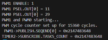
Since the pub and sub registers aren't zero it makes me believe that ppi is connected properly but the counter doesn't really count up. The statement TIMER2 live count: 0 keeps printing out and I cannot get the timer to start counting up, hence the callback never executes.
In case it matters, here's my proj.conf
CONFIG_LOG=y
CONFIG_LOG_DEFAULT_LEVEL=3


CONFIG_PWM=y
CONFIG_PWM_NRFX=y

CONFIG_PINCTRL=y
CONFIG_PINCTRL_NRF=y


CONFIG_COUNTER=y

CONFIG_GPIO=y

CONFIG_NRFX_TIMER2=y
CONFIG_PWM_LOG_LEVEL_DBG=y
CONFIG_COUNTER_LOG_LEVEL_DBG=y
CONFIG_ZERO_LATENCY_IRQS=y
and my overlay
&led0 {
	gpios = <&egpio 9 GPIO_ACTIVE_HIGH>;
};
&timer2 {
    status = "okay";
};
/ {
aliases {
pwm_generator = &pwm0;
pwm_cycle_counter = &timer2;
};
};
Some stuff in these is probably unnecessary but I don't think it should mess with anything.
If anyone used PPI before to interconnect two peripherals I'd be eternally grateful if you could provide an example of how you did it or if anyone knows what the issue in my code is, let me know.
Thank youuuuu
Jana

