nPM2100 ship/hibernate mode wake up issues

I've got some timing-issues with the nPM2100. As I could not locate the relevant information in the datasheet, I'm requesting this here.

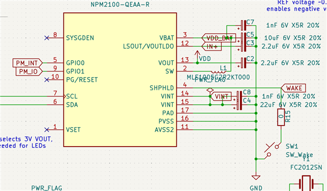
My PCB has an nPM2100 with a mechanical vibration sensor connected from SHPHLD to GND. GPIO0 is connected to a GPIO of a NRF54L15, which is powered by VOUT. I've configured GPIO as a OUTPUT and enabled SHPHLDFALL and SHPHLDRISE interrupts.

0x0A: 0b0000110 (RISE/FALL)
0x80: 0b0001010 (OUTPUT/PULLDOWN)
0x83: 0b0000010 (USAGE0 INT_HIGH)

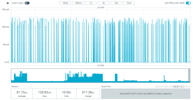
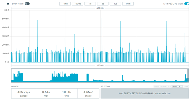
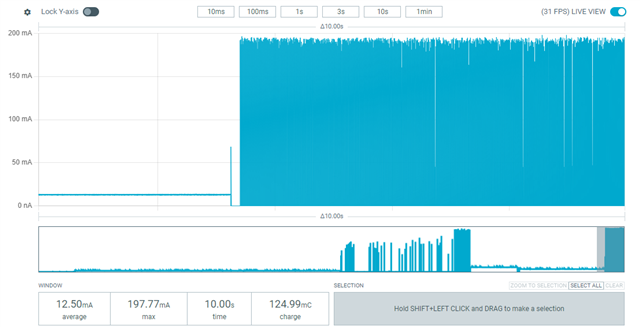
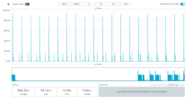
First mention. I really do not understand, why while in ship mode, the tPWROFF (wakeup time on SHPHLD low) is 2000ms (nRF1300 isn't). Couldn't this be programmable in series version? Right now, I need to use hibernate mode with debounce filter off, which gives expected results having higher energy consumption.

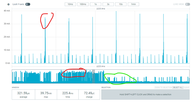
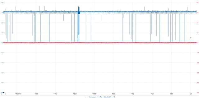
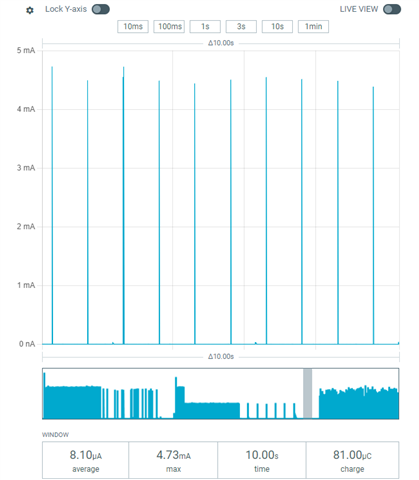
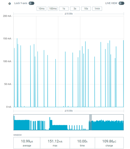
Second aspect is, that triggering the interrupt after SHPHLD edge takes 100ms. And further more, what's the time SHPHLD must be kept in switched level to be detected? The currently applied sensor only produces low-pulses of <20µs, which mostly does not get recognized by the nPM2100 (even with 0R series resistor). Can I apply a capacitor? What about leakage currents?

Any guide would be helpful. Thanks.

Parents
  • Hello,

    Note that SHPHLD pin is not a normal GPIO and has specific signal levels. Abs max of the SHPHLD is 1.9V and the high level threshold is fixed 0.6V. It is mainly designed for button use and not to be driven with active circuit which could drive it too high voltage and cause leakage. So care should be taken when checking the signal that comes from the vibration sensor.

    The wakeup time from Ship mode is 1000ms and unfortunately it is not programmable. The main use case is with a button, so the requirement comes from there.

    The 100ms delay you have experienced is due to the SHPHLD debounce time. The programming range is from 10ms to 3000ms and default is 100ms. You can set this with DEBOUNCE.TIME register. So this is the minimum time the signal must be low to be detected. You can also disable the debounce filter with DEBOUNCE.ENABLE bit if you like more immediate response.

    Thanks.

    -Tomi

  • Thanks for you quick reply. Now worries, our sensor only drives to ground (which I mentioned in my post).

    Could the wakeup time be made configurable in series production? "It is designed for button usage" is not that helpful as I was expecting...

    I missed to mention (sorry), that I already disabled the debounce timer with writing 0b00000000 to 0xCA. Didn't I? What's the minimum time required for detection when debounce timer is disabled?

  • Hello,

    Unfortunately in nPM2100 we don't have configurability for the wakeup time from ship mode. We can consider this for the upcoming devices.

    Ok if I understood correctly the wakeup happens almost immediately but there is still 100ms delay for the interrupt even if the hibernate mode debounce timer is disabled? So that is due to internal hard coded debounce timer (separate from the hibernate mode wake up timer), 100ms for SHPHLD button press and 10ms for release. Unfortunately no configurability for that.

    SHPHLD detection for wake up from hibernate mode is quite quick when the hibernate mode debounce timer is disabled. Typically it takes 13us from SHPHLD falling edge to start the VOUT turn on cycle. The detection is based on the internal 4MHz clock in case of hibernate mode (not hibernate_PT). And it needs up to 3 clock cycles to detect the signal. Note also the signal level that it goes low enough to be detected.

    Note the GPIO pull-down increases the current consumption when the signal is high.     

  • I made some improvements and I'm currently reading/clearing interrupt registers periodically to get the information I need.

    I'm into energy measurements again and I noticed, that shaking our vibration sensor leads to high energy consumption (in schematic it is connecting SHPHLD to GND with 0R, like mentioned in the reference design) of 30mA peaks (red markings). Without shaking, those peaks are gone. The peaks are in 30ms interval.

    Can you assist? Do I need apply a resistor? I think this could be problematic, as it would affect the wake-up.

  • Hello,

    What is the supply voltage and output voltage in this case? Do the current peaks align with the boost refresh cycles or TWI/INT/GPIO activity?

Reply Children
  • I think I found this issue, but directly went into the next one. GPIO was the hint you just gave. I think, the Interrupt GPIO I configured above has some failure, as it is always GND-level and therefore, when the SHPHLD triggered the GPIO, the consumption went up. I fixed this, by deactivating the GPIO as interrupt output.

    But now, I'm still unsure, whether the consumptions are as expected.

    During idling (no BLE, CPU sleeping in 10s interval with basically no operation) it draws 90µA with peaks of 120mA (measured at VBAT)

    With BLE active (using the nRF BLE tool) it rises to 460µA having peaks of 510mA:

    Schematic should be like reference design (won't be able to share publicly in full):

    As I do not now, what exactly is creating this peaky charging, I measured the voltage L1 (SW):

    I already replaced C5 and L1.

    Can you provide any hints?

  • Hello,

    It seems the inductor used in the schematic is not suitable for this device. Please see nPM2100 HW Design Guideline for more details on selecting the inductor: nPM2100 Hardware Design Guidelines

    Inductor saturation and high ESR will cause increased current consumption and high current spikes from the battery.

    If we assume you are using 1.5V battery and output voltage is set to 3V, the no load battery current of nPM2100 should be 200nA averaged over long period of time: So if it is in tens of uA range, that is too high. Higher current spikes are expected when the boost does the refresh cycle. The peak value depends on the input capacitor, but tens of mA is considered normal. Not sure about the load on the output can the current go there?

    GPIO configuration is also something worth checking. For example if the GPIO is set to CMOS output (not OD) and pull up/down resistor is activated, it will cause increased current consumption. Also check that the GPIO configs on both sides, host and PMIC side are set correctly to avoid the GPIOs fighting each other. IO levels on both sides should be also checked that they are compatible.

    Do you have nPM2100-EK you can use as reference to check the operation and current levels?

  • Ok, thank you for the hint. I currently applied: MLF1005G2R2KT000 TDK | Mouser Deutschland (2,2µF, DCR typ 1Ohm (quite high), max 30mA)

    I also tested the nPM2100-EK and turned on the low load (13mA at LDSW 1.8V VOUT). With VBAT=3.446V everything looks fine (BOOST is off). But with VBAT=1.2V the input current peaks to 200mA (at least average consumptions stays at 13mA):

    I found the guide you mentioned: Selecting inductors for the boost regulator

    As measuring consumptions on VDD and LDSW would be very hard, I thought it would be a good choice to start with measuring consumptions with having VBAT > VDD (3V). I started with VBAT = 3.446V, using the PPK2 as source. The power measurements are pretty clean now:

    Hibernate: 0.33µA | max 2.66µA

    High, BLE com: 640µA | max 92mA

    Now, there are two ways, I would go. (A) Select the correct inductor + (B) reduce energy consumption further more.

    (A) As I'm right now very limited to the footprint on my PCB (0402), I would try to grab those two from your recommendation: PLEA85DCA2R2M-1P, LSCNB1608HKT2R2MD. Or do you have some other suggestion?

    (B) there's still 105µA consumption, when LDSW is off and only nRF54L15 is idling in:

    k_event_wait(event, 0xFFF, false, timeout);

    I tried to set up theoretical consumptions from datasheet and some mearuements:

    nRF54L15 Consumption [mA] Interval [ms] Duration [ms]] Mean [mA]
    CPU Sleep 0,002 5000 4975 0,00199
    CPU 2,9 5000 25 0,0145
    Radio TX 9,8 500 2,4 0,04704
    SAADC 1,4 5000 5 0,0014
    Sensor 6,1 5000 20 0,0244
    0,08933

    All in all we should stay below 90µA mean (not 640µA). I would hope even less... But I can still tweak consumptions of Radio TX and Sensor. Any advice, how to check the CPU states/state times?

Related