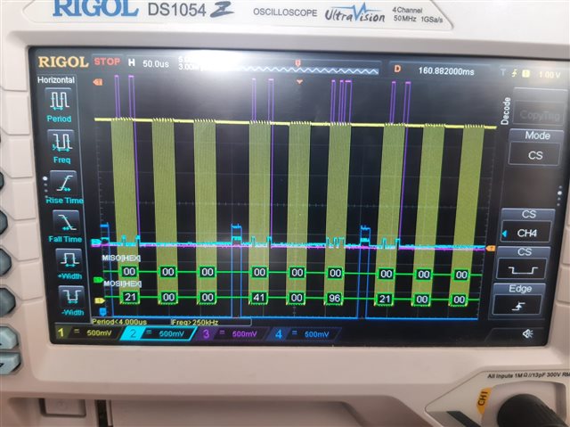
MISO line mimics the MOSI line in SPIM configuration sdk 17.1.0

Hi,

When I looked at the SPI lines using the oscilloscope, I saw that the MISO line had the same signal as the MOSI line. As you can see from the image, basically SPI configuration works properly. Before message transfer CS pin goes low, and after that, the MOSI line works. I can read message that I sent using the oscilloscope.
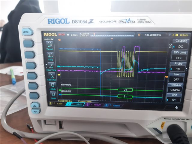
What can be the problem with the MISO line signal reflecting the MOSI line signal? The SPI config stage CPOL = 0, CPAH = 1, I am using a 2 MHz clock signal. Thanks for your help.

Parents
  • Schematic. Looks to me like MISO was never driven at all and is just floating. The voltage change results from coupling to MOSI and clock signal.

    MISO is supposed to be driven by the slave when CS=Low. Check that its properly connected. 

  • Sorry for the late response. All physical pins are connected properly, but I did not understand the problem. During the SPIM configuration, I just initialised the MISO pin. I am sharing my ADS1299 library code with you, Maybe the issue is about the software configuration of the SPIM. I checked the working mechanism of the SPI with ADS1299, and it looks like it was working properly. Again, thanks for your help.


    #include "ADS1299_nRF.h"
    #include <nrf.h>
    #include <nrf_log.h>
    #include <nrf_log_ctrl.h>
    #include <nrf_log_default_backends.h>
    #include <nrf_gpio.h>
    #include <nrf_delay.h>
    #include "ads1299_delay.h"
    
    // Enable polling mode for DRDY
    #define POLL_DREADY
    
    #define SPIM2 NRF_SPIM2
    
    bool new_data_available = false;
    uint8_t rx_buffer[27], tx_buffer[8];
    uint8_t sample_number = 0;
    static uint8_t regData[24]; // Mirror of ADS1299 registers
    
    
    /** @brief SPI interface initialization. Accurate timing use HFCLK clock */
    void spi_init(void) {
        // Start HFCLK source for accurate timing
        NRF_CLOCK->TASKS_HFCLKSTART = 1;
        while (NRF_CLOCK->EVENTS_HFCLKSTARTED == 0);
        NRF_CLOCK->EVENTS_HFCLKSTARTED = 0;
        
        // Disable SPIM to configure it
        SPIM2->ENABLE = (SPIM_ENABLE_ENABLE_Disabled << SPIM_ENABLE_ENABLE_Pos);
    
        // Configure SPIM2 pins
        SPIM2->PSEL.SCK = PIN_SCK;
        SPIM2->PSEL.MOSI = PIN_MOSI;
        SPIM2->PSEL.MISO = PIN_MISO;
        
        SPIM2->FREQUENCY = SPIM_FREQUENCY_FREQUENCY_M2; // 2 MHz
    
        // ADS1299 set Data mode clock polarity = 0; clock_phase = 1
        SPIM2->CONFIG = (SPIM_CONFIG_CPOL_ActiveLow << SPIM_CONFIG_CPOL_Pos) |  // Fixed CPOL
                        (SPIM_CONFIG_CPHA_Trailing << SPIM_CONFIG_CPHA_Pos) |
                        (SPIM_CONFIG_ORDER_MsbFirst << SPIM_CONFIG_ORDER_Pos);
    
        SPIM2->EVENTS_END = 0;
        SPIM2->EVENTS_ENDTX = 0;
        SPIM2->EVENTS_ENDRX = 0;
        SPIM2->EVENTS_STOPPED = 0;
    
        SPIM2->ENABLE = (SPIM_ENABLE_ENABLE_Enabled << SPIM_ENABLE_ENABLE_Pos);
        
    }
    
    static void spi_uninit(void) {
        SPIM2->ENABLE = (SPIM_ENABLE_ENABLE_Disabled << SPIM_ENABLE_ENABLE_Pos);
        nrf_gpio_cfg_input(PIN_SCK, NRF_GPIO_PIN_NOPULL);
        nrf_gpio_cfg_input(PIN_MOSI, NRF_GPIO_PIN_NOPULL);
        nrf_gpio_cfg_input(PIN_MISO, NRF_GPIO_PIN_NOPULL);
    }
    
    //bool spi_transfer_byte(uint8_t tx, uint8_t *rx) {
    //    uint8_t local_rx = 0;
    //    if (!rx) rx = &local_rx;
    //    if (!(SPIM2->ENABLE & SPIM_ENABLE_ENABLE_Msk)) {
    //        SPIM2->ENABLE = (SPIM_ENABLE_ENABLE_Enabled << SPIM_ENABLE_ENABLE_Pos);
    //    }
    //    SPIM2->TXD.PTR = (uint32_t)&tx;
    //    SPIM2->TXD.MAXCNT = 1;
    //    SPIM2->RXD.PTR = (uint32_t)rx;
    //    SPIM2->RXD.MAXCNT = 1;
    //    SPIM2->EVENTS_END = 0;
    //    SPIM2->TASKS_START = 1;
    
    //    nrf_delay_us(20);
    
    //    //uint32_t timeout = 10000;
    //    //while (!SPIM2->EVENTS_END && timeout--) {
    //    //    nrf_delay_us(1);
    //    //}
    //    //if (timeout == 0) {
    //    //    NRF_LOG_ERROR("SPI transfer timeout");
    //    //    return false;
    //    //}
    //    SPIM2->EVENTS_END = 0;
    //    NRF_LOG_INFO("SPI TX: 0x%02x, RX: 0x%02x", tx, *rx);
    //    return true;
    //}
    
    uint8_t spi_transfer_byte(uint8_t tx) {
        uint8_t rx;
        if (!(SPIM2->ENABLE & SPIM_ENABLE_ENABLE_Msk)) {
            SPIM2->ENABLE = (SPIM_ENABLE_ENABLE_Enabled << SPIM_ENABLE_ENABLE_Pos);
        }
        SPIM2->TXD.PTR = (uint32_t)&tx;
        SPIM2->TXD.MAXCNT = 1;
        SPIM2->RXD.PTR = (uint32_t)&rx;
        SPIM2->RXD.MAXCNT = 1;
        SPIM2->EVENTS_END = 0;
        SPIM2->TASKS_START = 1;
        while (!SPIM2->EVENTS_END);
        SPIM2->EVENTS_END = 0;
        //SPIM2->TASKS_STOP = 1;
        NRF_LOG_INFO("SPI TX: 0x%02x, RX: 0x%02x", tx, rx);
        return rx;
    }
    
    bool spi_transfer_byte_v2(uint8_t tx, uint8_t *rx) {
        uint8_t local_rx = 0;
        if (!rx) rx = &local_rx;
        
        // Ensure SPIM2 is enabled (assumes prior configuration)
        if (!(SPIM2->ENABLE & SPIM_ENABLE_ENABLE_Msk)) {
            SPIM2->ENABLE = (SPIM_ENABLE_ENABLE_Enabled << SPIM_ENABLE_ENABLE_Pos);
        }
        
        // Clear events before starting
        SPIM2->EVENTS_ENDTX = 0;
        SPIM2->EVENTS_ENDRX = 0;
        SPIM2->EVENTS_END = 0;
        
        // Configure buffers
        SPIM2->TXD.PTR = (uint32_t)&tx;
        SPIM2->TXD.MAXCNT = 1;
        SPIM2->RXD.PTR = (uint32_t)rx;
        SPIM2->RXD.MAXCNT = 1;
        
        // Start transaction
        SPIM2->TASKS_START = 1;
        
        // Wait for transaction to complete
        while (!SPIM2->EVENTS_END);
        
        // Clear events
        SPIM2->EVENTS_ENDTX = 0;
        SPIM2->EVENTS_ENDRX = 0;
        SPIM2->EVENTS_END = 0;
    
        NRF_LOG_INFO("SPI TX: 0x%02x, RX: 0x%02x", tx, *rx);
        return true;
    }
    
    bool ADS1299_init(void) {
        
        // recommended power up sequence for ADS1299
        delay_init();
        nrf_delay_ms(50);
        
        NRF_LOG_INFO("Initializing ADS1299");
        nrf_gpio_pin_clear(RESET_PIN);
        nrf_gpio_cfg_output(RESET_PIN);
        nrf_gpio_pin_clear(RESET_PIN);
        nrf_delay_us(4);
        nrf_gpio_pin_set(RESET_PIN);
        nrf_delay_us(20);
        
        //nrf_gpio_cfg_output(PIN_SCK);
        //nrf_gpio_cfg_output(PIN_MOSI);
        
        //nrf_gpio_pin_clear(PIN_SCK);
        //nrf_gpio_pin_clear(PIN_MOSI);
        
        spi_init();
    
        nrf_gpio_cfg_input(PIN_DRDY,NRF_GPIO_PIN_NOPULL);
    
        nrf_gpio_pin_set(CS_PIN);
        //NRF_GPIO->PIN_CNF[CS_PIN] = (GPIO_PIN_CNF_DIR_Output << GPIO_PIN_CNF_DIR_Pos) |
        //                            (GPIO_PIN_CNF_DRIVE_S0S1 << GPIO_PIN_CNF_DRIVE_Pos) |
        //                            (GPIO_PIN_CNF_INPUT_Connect << GPIO_PIN_CNF_INPUT_Pos) |
        //                            (GPIO_PIN_CNF_PULL_Disabled << GPIO_PIN_CNF_PULL_Pos) |
        //                            (GPIO_PIN_CNF_SENSE_Disabled << GPIO_PIN_CNF_SENSE_Pos);
    
        nrf_gpio_cfg_output(CS_PIN);
    
        nrf_gpio_pin_set(CS_PIN);
        nrf_gpio_pin_set(RESET_PIN);
    
        NRF_LOG_INFO("SPI init success");
    #ifdef POLL_DREADY
        NRF_LOG_INFO("DRDY polling enabled");
    #else
        NRF_LOG_INFO("DRDY interrupt not implemented");
    #endif
        return true;
    }
    
    void poll_dready(void) {
    #ifdef POLL_DREADY
        NRF_LOG_INFO("Polling DRDY, state: %d", nrf_gpio_pin_read(PIN_DRDY));
        if (nrf_gpio_pin_read(PIN_DRDY) == 0) {
            NRF_LOG_INFO("DRDY low, receiving data");
            ADS1299_receive_data();
            send_new_available_data();
        }
    #endif
    }
    
    bool ADS1299_write_register(uint8_t address, uint8_t value) {
    
        uint8_t opcode1 = address | COMMAND_WREG;
        nrf_gpio_pin_clear(CS_PIN);
    
        //if (!spi_transfer_byte_v2(opcode1, NULL)) {
        //    nrf_gpio_pin_set(CS_PIN);
        //    return false;
        //}
        //if (!spi_transfer_byte_v2(0x00, NULL)) {
        //    nrf_gpio_pin_set(CS_PIN);
        //    return false;
        //}
        //if (!spi_transfer_byte_v2(value, NULL)) {
        //    nrf_gpio_pin_set(CS_PIN);
        //    return false;
        //}
        
        spi_transfer_byte(opcode1);
        spi_transfer_byte(0x00);
        spi_transfer_byte(value);
        nrf_delay_us(4);
        nrf_gpio_pin_set(CS_PIN);
        regData[address] = value;
        
        
        return true;
    }
    
    bool ADS1299_read_register(uint8_t address, uint8_t *value) {
        uint8_t opcode1 = address | COMMAND_RREG;
        
        nrf_gpio_pin_clear(CS_PIN);
    
        //if (!spi_transfer_byte_v2(opcode1, NULL)) {
        //    nrf_gpio_pin_set(CS_PIN);
        //    return false;
        //}
        //if (!spi_transfer_byte_v2(0x00, NULL)) {
        //    nrf_gpio_pin_set(CS_PIN);
        //    return false;
        //}
        //if (!spi_transfer_byte_v2(0x00, value)) {
        //    nrf_gpio_pin_set(CS_PIN);
        //    return false;
        //}
        
        spi_transfer_byte(opcode1);
        spi_transfer_byte(0x00);
        *value = spi_transfer_byte(0x00);
    
        nrf_delay_us(4);
    
        nrf_gpio_pin_set(CS_PIN);
    
        regData[address] = *value;
        
        return true;
    }
    
    bool ADS1299_send_command(uint8_t command) {
        uint8_t dummy;
        nrf_gpio_pin_clear(CS_PIN);
        //if (!spi_transfer_byte_v2(command, &dummy)) {
        //    NRF_LOG_ERROR("Failed to send command 0x%02x", command);
        //    nrf_gpio_pin_set(CS_PIN);
        //    return false;
        //}
        spi_transfer_byte(command);
    
        nrf_delay_us(4);
        nrf_gpio_pin_set(CS_PIN);
        return true;
    }
    
    bool ADS1299_send_start(void) {
    
        bool result = ADS1299_send_command(COMMAND_START);    
        return result;
    }
    
    bool ADS1299_send_read_continuous(void) {
        bool result = ADS1299_send_command(COMMAND_RDATAC);
        nrf_delay_us(3);
        return result;
    }
    
    bool ADS1299_send_reset(void) {
        //nrf_gpio_pin_clear(CS_PIN);
        bool result = ADS1299_send_command(COMMAND_RESET);
        nrf_delay_us(20);
        //nrf_gpio_pin_set(CS_PIN);
        NRF_LOG_INFO("Reset command sent, result: %d", result);
        return result;
    }
    
    bool ADS1299_send_sdatac(void) {
        //nrf_gpio_pin_clear(CS_PIN);
        bool result = ADS1299_send_command(COMMAND_SDATAC);
        //nrf_gpio_pin_set(CS_PIN);
        nrf_delay_ms(10);
        NRF_LOG_INFO("Stop read continuously command sent, result: %d", result);
        return result;
    }
    
    bool ADS1299_receive_data(void) {
        new_data_available = false;
        if (!spi_transfer_bytes(NULL, rx_buffer, 27)) {
            NRF_LOG_ERROR("Failed to receive data");
            return false;
        }
        new_data_available = true;
        NRF_LOG_INFO("Data received, triggering send_new_available_data");
        return true;
    }
    
    bool ADS1299_poll_new_data(ADS1299_data_t *data) {
        if (new_data_available) {
            new_data_available = false;
            *data = ADS1299_convert_data();
            return true;
        }
        return false;
    }
    
    static inline int32_t buffer_to_channel(uint8_t id) {
        int32_t value = (rx_buffer[3 + id * 3] << 16) | (rx_buffer[4 + id * 3] << 8) | rx_buffer[5 + id * 3];
        if (value & 0x00800000) {
            value |= 0xFF000000;
        } else {
            value &= 0x00FFFFFF;
        }
        return value;
    }
    
    ADS1299_data_t ADS1299_convert_data(void) {
        ADS1299_data_t data;
        data.lead_off_positive = rx_buffer[0] << 4;
        data.lead_off_positive |= (rx_buffer[1] & 0b11110000) >> 4;
        data.lead_off_negative = rx_buffer[1] << 4;
        data.lead_off_negative |= (rx_buffer[2] & 0b11110000) >> 4;
        data.gpio_0 = rx_buffer[2] & 0b00001000;
        data.gpio_1 = rx_buffer[2] & 0b00000100;
        data.gpio_2 = rx_buffer[2] & 0b00000010;
        data.gpio_3 = rx_buffer[2] & 0b00000001;
        data.channel_0 = buffer_to_channel(0);
        data.channel_1 = buffer_to_channel(1);
        data.channel_2 = buffer_to_channel(2);
        data.channel_3 = buffer_to_channel(3);
        data.channel_4 = buffer_to_channel(4);
        data.channel_5 = buffer_to_channel(5);
        data.channel_6 = buffer_to_channel(6);
        data.channel_7 = buffer_to_channel(7);
        return data;
    }
    
    void send_new_available_data(void) {
        if (new_data_available) {
            new_data_available = false;
            NRF_LOG_INFO("Sample: %d", sample_number++);
            for (uint8_t i = 0; i < 27; i++) {
                NRF_LOG_INFO("Byte %d: 0x%02x", i, rx_buffer[i]);
            }
        }
    }

  • Can it be that you have some capacitive coupling between the two lines, such that when MOSI is driven, this is "reflected" on the MISO (presuming nothing is actually driving the MISO line externally in this case).

    Kenneth

  • Basically, the MISO line must be driven by ADS1299. The master side works as I expected when I looked at the configuration of the SPIM. So, do you have any offer to eliminate this capacitive coupling problem? Did you see any misconfiguration of the SPIM?

  • The SPIM pins do not appear to be correctly set in the code posted above; the pins should be set prior to allocating via PSEL. The ADS1298/9 has peculiar requirements, and rather than repeating them here have a look at this discussion where I posted some of my findings (and quite a few others search for ADS1298 or ADS1299):

    problem-using-the-nrf52840-to-interface-an-ads1298-via-spi

  • Thanks for your reply. After reading the discussion that you share, I will update my findings.

Reply Children
  • Apart from all the devzone posts we've made over the years on the ADS129x some of these older links might be worth looking at:

    5809-biopotential-signal-library

    starcat/hackeeg

    stm32-diy-board-with-ads1299-sparkyeeg

    openeeg.sourceforge.net

  • Hi, Hmolesworth. I configured SPI pins before assigning them via PSEL, but nothing changed.  I have read the discussion you shared and added some related parts to the code. So, I am seeing just 0x00. I do not know what I should do. Are there any other offers to help find a solution to this problem?

    With the latest config, I am seeing this. 

    Turquoise -> MISO
    Purple -> MOSI

    Yellow-> Clock
    Dark Blue -> CS


  • The display would be easier to read if you could separate the traces so they don't overlap. In case you are using S0S1 (default SPIM drive settings), always start with H0H1; try this perhaps:

        // Set High-drive pin mode for SPI
        nrf_gpio_cfg(PIN_SCK,  NRF_GPIO_PIN_DIR_OUTPUT, NRF_GPIO_PIN_INPUT_CONNECT, NRF_GPIO_PIN_PULLUP, NRF_GPIO_PIN_H0H1, NRF_GPIO_PIN_NOSENSE);
        nrf_gpio_cfg(PIN_MOSI, NRF_GPIO_PIN_DIR_OUTPUT, NRF_GPIO_PIN_INPUT_CONNECT, NRF_GPIO_PIN_PULLUP, NRF_GPIO_PIN_H0H1, NRF_GPIO_PIN_NOSENSE);
        nrf_gpio_cfg(PIN_CS,   NRF_GPIO_PIN_DIR_OUTPUT, NRF_GPIO_PIN_INPUT_CONNECT, NRF_GPIO_PIN_PULLUP, NRF_GPIO_PIN_H0H1, NRF_GPIO_PIN_NOSENSE);

    PULLUP is not strictly necessary, NOPULL could be used instead; H0H1 is the important part.

    Worth also trying to start with a slower clock before increasing clock rate:

            spi_config.frequency = NRF_DRV_SPI_FREQ_500K;  // Ensure less than 4 clk cycles for ADS1292
            spi_config.bit_order = NRF_DRV_SPI_BIT_ORDER_MSB_FIRST;
            spi_config.mode      = NRF_DRV_SPI_MODE_1;
            APP_ERROR_CHECK(nrf_drv_spi_init(&mAfeSpiInstance, &spi_config, afe_spi_event_handler, NULL));
    

    The different parts require power-up handling, as an example:

            // Enable ADS1292 AFE - Power on & remove reset
            nrf_delay_ms(ADS_POWER_RAMP_TIME_MSECS); // Delay about 30 msecs to allow regulator to charge capacitance
            DEACTIVATE_ADS_RESET_PIN;           // Release active-low combined /Reset and /Powerdown
            nrf_delay_ms(1000);                 // Delay 1 sec as per data sheet
            ACTIVATE_ADS_RESET_PIN;             // Activate active-low combined /Reset and /Powerdown
            nrf_delay_ms(2);                    // Delay to allow ADS internal clock to start
            DEACTIVATE_ADS_RESET_PIN;           // Release active-low combined /Reset and /Powerdown
            nrf_delay_us(200);                  // Delay to allow 18 tclk minimum
    
        AdsReset();                                      // Reset ADS
        AdsSendCmd(ADS_CMND_SDATAC);                     // Stop continuous mode
    

    This is a bare-bones segment (ADS1292, similar) in case it's of any help:

    // The SPI master implements EasyDMA for reading and writing of data packets from and to the DATA RAM
    // without CPU involvement.
    // The RXD.PTR and TXD.PTR point to the RXD buffer (receive buffer) and TXD buffer (transmit buffer)
    // respectively. RXD.MAXCNT and TXD.MAXCNT specify the maximum number of bytes allocated to the buffers.
    // The SPI master will automatically stop transmitting after TXD.MAXCNT bytes have been transmitted and
    // RXD.MAXCNT bytes have been received. If TXD.MAXCNT is larger than RXD.MAXCNT, the superfluous
    // received bytes will be ignored. If RXD.MAXCNT is larger than TXD.MAXCNT, the remaining transmitted
    // bytes will contain the value defined in the ORC register.
    // If the RXD.PTR and the TXD.PTR are not pointing to the Data RAM region, an EasyDMA transfer may result
    // in a HardFault or RAM corruption.
    // The .PTR and .MAXCNT registers are double-buffered. They can be updated and prepared for the next
    // transmission immediately after having received the STARTED event.
    // The ENDRX/ENDTX event indicate that EasyDMA has finished accessing respectively the RX/TX buffer in
    // RAM. The END event gets generated when both RX and TX are finished accessing the buffers in RAM.
    // EasyDMA array list
    // The EasyDMA array list can be represented by the data structure ArrayList_type. This data structure
    // includes only a buffer with size equal
    // to Channel.MAXCNT. EasyDMA will use the Channel.MAXCNT register to determine when the buffer
    // is full. Replace 'Channel' by the specific data channel you want to use, for instance 'NRF_SPIM->RXD',
    // 'NRF_SPIM->TXD', 'NRF_TWIM->RXD', etc.
    // The Channel.MAXCNT register cannot be specified larger than the actual size of the buffer. If
    // Channel.MAXCNT is specified larger than the size of the buffer, the EasyDMA channel may overflow the
    // buffer.
    // This array list does not provide a mechanism to explicitly specify where the next item in the list is located.
    // Instead, it assumes that the list is organized as a linear array where items are located one after the other in
    // RAM.
    //
    // SPI master transaction sequence
    // ===============================
    // An SPI master transaction consists of a sequence started by the START task followed by a number of
    // events, and finally the STOP task.
    // An SPI master transaction is started by triggering the START task. The ENDTX event will be generated
    // when the transmitter has transmitted all bytes in the TXD buffer as specified in the TXD.MAXCNT register.
    // The ENDRX event will be generated when the receiver has filled the RXD buffer, i.e. received the last
    // possible byte as specified in the RXD.MAXCNT register.
    // Following a START task, the SPI master will generate an END event when both ENDRX and ENDTX have
    // been generated.
    // The SPI master is stopped by triggering the STOP task. A STOPPED event is generated when the SPI
    // master has stopped.
    // If the ENDRX event has not already been generated when the SPI master has come to a stop, the SPI
    // master will generate the ENDRX event explicitly even though the RX buffer is not full.
    // If the ENDTX event has not already been generated when the SPI master has come to a stop, the SPI
    // master will generate the ENDTX event explicitly even though all bytes in the TXD buffer, as specified in the
    // TXD.MAXCNT register, have not been transmitted.
    // The SPI master is a synchronous interface, and for every byte that is sent, a different byte will be received at
    // the same time
    //
    // Master mode pin configuration
    // =============================
    // The SCK, MOSI, and MISO signals associated with the SPI master are mapped to physical pins according to
    // the configuration specified in the PSEL.SCK, PSEL.MOSI, and PSEL.MISO registers respectively.
    // The PSEL.SCK, PSEL.MOSI, and PSEL.MISO registers and their configurations are only used as long as
    // the SPI master is enabled, and retained only as long as the device is in ON mode. PSEL.SCK, PSEL.MOSI
    // and PSEL.MISO must only be configured when the SPI master is disabled.
    // To secure correct behavior in the SPI, the pins used by the SPI must be configured in the GPIO peripheral
    #if defined(USING_NORDIC_SPIM_DRIVERS)
    #else
    static void spiInit(NRF_SPIM_Type * const pSPIM, const IRQn_Type IRQn, const uint32_t IRQpriority)
    {
    //spi_config.mode      = NRF_DRV_SPI_MODE_1;
      pSPIM->ENABLE = 0;                        // disable SPI
      NRF_P0->PIN_CNF[ADS_CS_PIN]   = 0x301;  // output, high drive high and low H0H1
      NRF_P0->PIN_CNF[ADS_SCK_PIN]  = 0x301;  // output, high drive high and low H0H1
      NRF_P0->PIN_CNF[ADS_MOSI_PIN] = 1;      // output, standard drive S0S1
      NRF_P0->PIN_CNF[ADS_MISO_PIN] = 0;      // input pin, input buffer connected, no pull, S0S1, sense disabled
      NRF_P0->OUTSET = 1 << ADS_CS_PIN;       // deactivate by setting chip select high
      pSPIM->PSEL.SCK   = ADS_SCK_PIN;
      pSPIM->PSEL.MOSI  = ADS_MOSI_PIN;
      pSPIM->PSEL.MISO  = ADS_MISO_PIN;
      pSPIM->CONFIG = 2;                  // CPOL 0 -- clock polarity active high, CPHA 1 -- sample on trailing clock edge, send Msb first
      pSPIM->FREQUENCY = NRF_DRV_SPI_FREQ_500K;  // Ensure less than 4 clk cycles for ADS1292
      pSPIM->ORC = 0xFF;                     // Unused Tx bytes, set all bits high
    
      pSPIM->EVENTS_ENDTX = 0;
      pSPIM->EVENTS_ENDRX = 0;
      pSPIM->EVENTS_END   = 0;
      // Disable all interrupts
      pSPIM->INTENCLR = 0xFFFFFFFFUL;
      // Enable selected interrupts
      pSPIM->INTENSET = 0x040;   // END
      //pSPIM->INTENSET = 0x010;   // END_RX
      //pSPIM->INTENSET = 0x100;   // END_TX
      
      // Set interrupt priority and enable interrupt
      NVIC_SetPriority(IRQn, IRQpriority);
      NVIC_ClearPendingIRQ(IRQn);
      NVIC_EnableIRQ(IRQn);
    
      mSpiInterruptCounter = 0UL;
      pSPIM->ENABLE = 7;               // enable SPI
    }
    
    static void spiTransfer(uint8_t const * p_tx_buffer,
                            uint8_t         tx_buffer_length,
                            uint8_t       * p_rx_buffer,
                            uint8_t         rx_buffer_length)
    {
      NRF_SPIM0->EVENTS_ENDTX = 0;
      NRF_SPIM0->EVENTS_ENDRX = 0;
      NRF_SPIM0->EVENTS_END   = 0;
    
      NRF_SPIM0->ENABLE = 7;               // enable SPI
      NRF_SPIM0->TXD.PTR = (uint32_t)p_tx_buffer;
      NRF_SPIM0->TXD.MAXCNT = tx_buffer_length;
      NRF_SPIM0->RXD.PTR = (uint32_t)p_rx_buffer;
      NRF_SPIM0->RXD.MAXCNT = rx_buffer_length;
      NRF_P0->OUTCLR = 1 << ADS_CS_PIN;    // drive cs low to initiate spi comm
      nrf_delay_us(10);
      NRF_SPIM0->TASKS_START = 1;
      while(!NRF_SPIM0->EVENTS_ENDTX);     // last byte transmitted
      while(!NRF_SPIM0->EVENTS_ENDRX);     // last byte received
      NRF_SPIM0->TASKS_STOP = 1;
      nrf_delay_us(10);
      NRF_P0->OUTSET = 1 << ADS_CS_PIN;
      while(!NRF_SPIM0->EVENTS_STOPPED);
      //NRF_SPIM0->ENABLE = 0;               // disable SPI
    }
    

  • Thanks for your quick reply, hmolesworth. I tried adding reasonable delays to the power-up sequence, but I am getting the same signal from the MISO line. I have seen articles about power in different places. I am not using power for ADS1299 via nRF. Could this be causing the problem? I am powering the ADS1299 DK with an external device. I tried with a lower clock frequency, but it did not change anything. Again, thanks for your reply.

Related