MISO line mimics the MOSI line in SPIM configuration sdk 17.1.0

Hi,

When I looked at the SPI lines using the oscilloscope, I saw that the MISO line had the same signal as the MOSI line. As you can see from the image, basically SPI configuration works properly. Before message transfer CS pin goes low, and after that, the MOSI line works. I can read message that I sent using the oscilloscope.
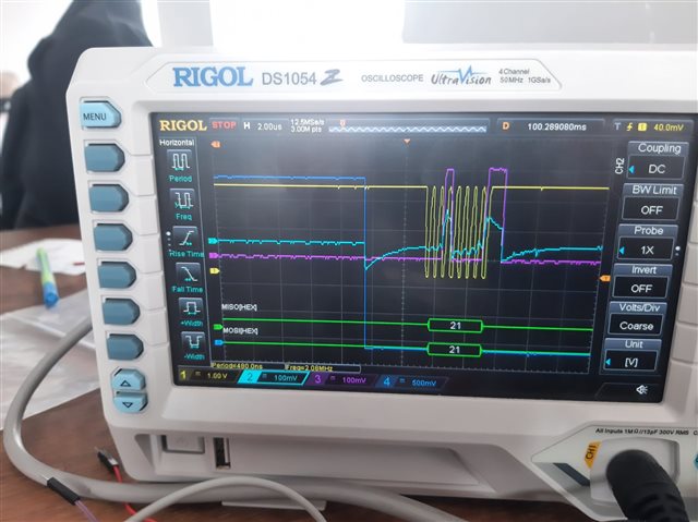
What can be the problem with the MISO line signal reflecting the MOSI line signal? The SPI config stage CPOL = 0, CPAH = 1, I am using a 2 MHz clock signal. Thanks for your help.

  • "To secure correct behavior in the SPI, the pins used by the SPI must be configured in the GPIO peripheral as described in Table 69: GPIO configuration on page 288 prior to enabling the SPI."

    CS, SCLK, MOSI and MISO pins must all be configured before the SPI is enabled; your code has these commented out. Additionally to start testing don't use SPIM_FREQUENCY_FREQUENCY_M4 but instead start with 500KHZ and only try to use a faster clock speed once you have basic functionality.

  • I modified the code based on your suggestion. According to the datasheet of the ADS1299, after the power-up sequence, ADS1299 enters RDATAC mode. I checked the DRDY pin, but there are no DRDY pulses after the power-up sequence. I am confident the power-up sequence works correctly because during this process, VCAP1 rises above 1.1v. Additionally, on the TI website, it states that after the power-up sequence, VCAP2 should be (AVDD-AVSS)/2, but it shows 0v. Could this be the issue? 

    Edit:
    When I give the START pin a high voltage, the DRDY pin starts to toggle.

  • Hello  . Did you have a chance to check the outputs I specified? As I mentioned, when I set the START pin to high voltage, the DRDY pin begins toggling, but I don't observe such a toggle after the power-up sequence. Additionally, this site states that VCAP2 should be (AVDD + AVSS)/2, but it displays 0V. Thank you for your response.

  • A schematic would help. To get going in unipolar supply mode all these pins must be connected:

     AVDD = AVDD1 = VREFP = +5V so Pins 19,21,22,24,54,56,59 all connected together

    AVSS = AVSS1 = DGND = RESV1 = AGND = VREFN = nRF52 GND so Pins 20,23,25,32,33,49,51,53,57,58 all connected together

    DVDD = nRF52 3.3V or 3.0V so Pins 48,50 connected together

    VCAP1, VCAP2, VCAP3, VCAP4 all require appropriate capacitors to AVSS

    By default, the device wakes up in external reference mode which is why VREFP can be connected to AVDD.

  • Thank you for your expert opinions  . I have resolved the SPI communication issue between ADS1299 and nRF52. Now, I can establish communication between the two devices. The problem was caused by an incorrect power supply to ADS1299. Additionally, the issue with the DK board was due to the incorrect connection you mentioned for JP21. I realised that it prevented connection with the device because it couldn't activate the CS pin. It really bothered me to deal with such simple issues for so long, but I appreciate everything.

Related