MISO line mimics the MOSI line in SPIM configuration sdk 17.1.0

Hi,

When I looked at the SPI lines using the oscilloscope, I saw that the MISO line had the same signal as the MOSI line. As you can see from the image, basically SPI configuration works properly. Before message transfer CS pin goes low, and after that, the MOSI line works. I can read message that I sent using the oscilloscope.
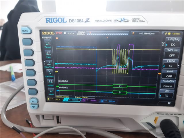
What can be the problem with the MISO line signal reflecting the MOSI line signal? The SPI config stage CPOL = 0, CPAH = 1, I am using a 2 MHz clock signal. Thanks for your help.

  • Based on the traces, J2 is not connected because I am not using the MMB0 board. Therefore, I am connecting 5V to the third pin of JP2. I believed that when I connect 5V this way, it would supply power to the board. Thank you for clarifying the SPI_CS. Following that, I moved the SPI_CS pin to the third pin of JP21. Thanks for your reply  .

  • Edit: Photo shows J2 but I misread your last post - I see you now have JP2 not J2

    J2 is only present for physically attaching to MMB0 board; there are no electrical connections to J2 on the ADS board according to the ADS schematic. The MMBO 20-pin connectors are connected in parallel, but ADS J2 goes nowhere. For reference this is the MMBO schematic:

    1121.MMB0_Sch_RevD.PDF

  • Thanks for your reply  . I am taking up too much of your time. So basically, I want to discuss the general following path of the configuration. Using the same configuration architecture, I created a simple SPI test with nRF52840DK as the master and Arduino Uno as the slave. As a result, I achieved successful communication between them. I can now read and write values to the Arduino Uno via nRF52840. On the other hand, ADS1299 configuration fails every time. According to our discussion, we end up with a power management problem. 

    The point I want to make is that, if I follow the path I have outlined below, can I also establish communication between the ADS1299 and the nRF52840? If the problem I am experiencing is not a configuration problem, can I get a system ready for communication once I solve the power problem?


    Thanks for your reply.

  • Yes. Also note JP2 pins 1 and 3 rely on an external 5V supply which is required. Good luck ..

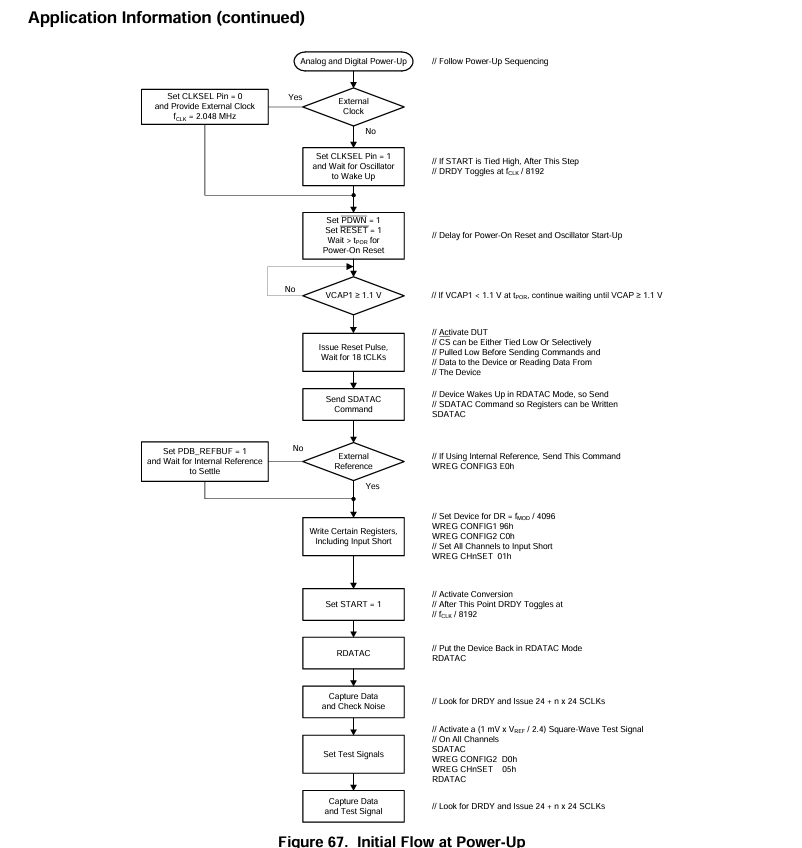
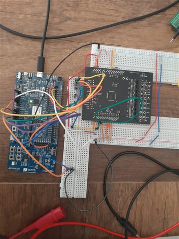
  • Sorry to bother you again  . I have a new board. I am feeding the AVDD with 5V and the DVDD with 3V from the nRF52840DK. I know the picture doesn't help, but I put the ADS1299 chip on the board and brought all the pins out. So, I am getting this result: MISO line returns 0x00 all the time, but it shows like toggling. I am supplying voltages from the nRF52840DK. I am using 5V to 0 as an AVDD-AVSS. I cannot get any response. I controlled VCAP1, and I measured it as 1.2V. Really, I do not understand where the problem is. I did not change anything in my code.


Related