nRF21540 FEM TX Power with ESB

We are currently working on a project using Enhanced ShockBurst (ESB) and would like to enable Front-End Module (FEM) support with the nRF21540.

According to the Enhanced ShockBurst sample documentation, FEM support is available.
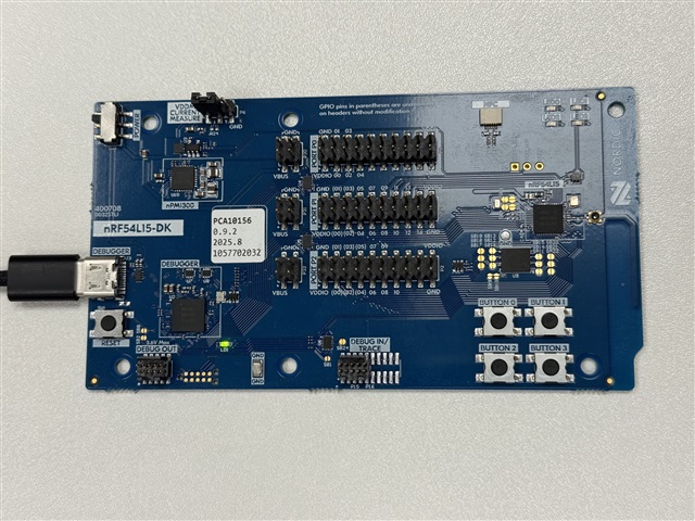
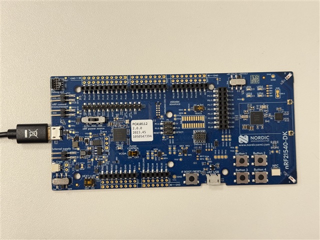
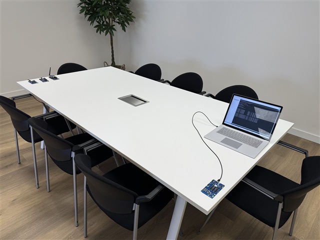
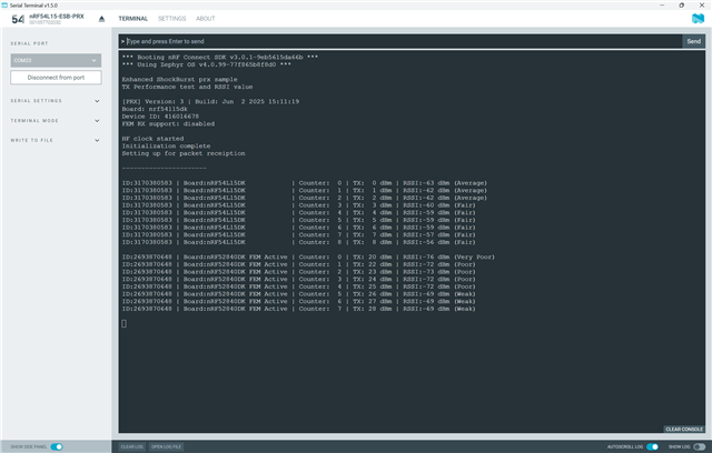
I have modified the standard esb_ptx and esb_prx examples to test the various TX power levels supported by different Nordic boards and to observe the resulting RSSI values on the receiving side. This allows me to test range and determine which Nordic chip or antenna performs best and which TX power level is required for stable communication.

FEM Support:

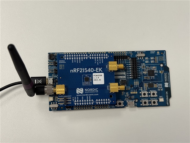
The modified example works well in general, but I see no improvement when using an nRF21540-DK or any other Nordic board equipped with the nRF21540-EK shield.

I’ve carefully followed all documentation and Q&A posts on Nordic Developer Zone. I have enabled the necessary MPSL drivers and configured the correct overlay settings for FEM support.

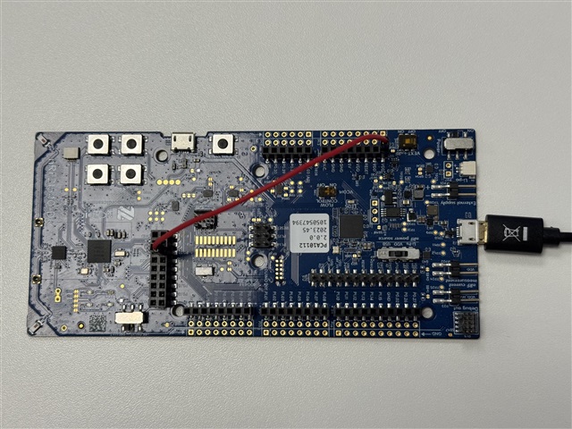
However, on the nRF21540-DK, the signal is so weak that I can only transmit packets if the PTX and PRX boards are placed directly next to each other. It doesn’t seem to make a difference whether MPSL is enabled or not.

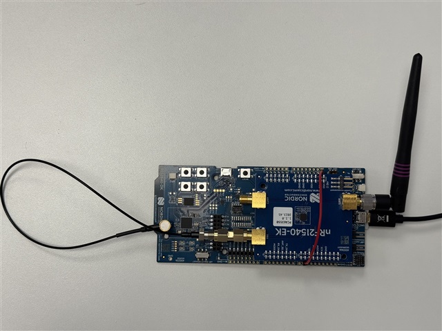
With other boards like the nRF52840 + nRF21540-EK shield, the received signal is also significantly worse compared to using no FEM at all.

I’ve spent quite some time on this and have a decent amount of experience with the Nordic platform, but I just can’t get FEM to work properly with the ESB protocol using the nRF Connect SDK 3.0.1.

So I’m wondering:

  • Am I missing something in the configuration?

  • Could there be a software or driver issue?

  • Or is there possibly something wrong with the hardware?

I’ve attached my ESB RSSI test project, along with the console output for different Nordic development boards. Feel free to use this example for other purposes—it can be helpful to quickly test RSSI across various boards and antenna setups at different distances.


Sample: ESB-RSSI (version 18-06-2025).zip

Parents
  • Hello,

    Thank you for providing the sample projects. From the PTX project I see that you have implemented a function named tx_power_supported() which checks whether the requested output power is supported by the nRF RADIO. However, this does not apply when using the FEM, as the MPSL library will always attempt to achieve the requested output power by adjusting the RADIO TX gain, see TX power split.

    Best regards,

    Vidar

  • Hi Vidar,

    thanks for your response. This is known to me — as you can see in my code, I add the FEM’s TX power also to the value. So I am taking that into total value. This is purely for reference, and I also include it in the ESB packet so that on the other side I can also see with which TX power value something was sent. But the main issue is that my RSSI value is lower when I activate MPSL.

  • Hello Herke,
    Vidar asked me to have a look at your questions as the description of "signal so weak that I can only transmit packets if the PTX and PRX are placed directly next to each other". This is the same behaviour I would expect if for some reason the antenna on one (or both) of the boards was missing. The matching network and board itself will radiate enough that it will be transmit a very short distance.
    Q1: The FW without the FEM works ok, if I understand you correctly?
    Q2: Could you send a picture of the actual PTX and PRX boards and setup you are using? 
    Q3: Are you manually connecting the FEM between the non-FEM tests and the tests with FEM?
    Q4: It sounds like you have several boards available, what RSSI readings are you actually seeing on the PRX when you are not using the FEM and at what distance would that be? How does this change when you add the FEM with same distance and location?
    I suspect there's something with the connection that is causing this based on the description. If you are able to get packets through at very short distances with FEM and "normal" 10-20meter range when there's no FEM, with the same FW, I'd check the connections through the FEM. If you have a FEM on both sides, I'd debug with just one side first to see if it's the PRX or PTX to narrow it down.
    Best regards
    Asbjørn
  • Dear Asbjørn,
    Sorry for my late reply — I was abroad for a while. Today I took some time to make a few photos of the test setup.
    Here are the answers to your questions:

    Q1: The firmware without FEM works fine.
    Q2: I've taken several photos of the test setup — see attachments.
    Q3: I have about 20 Nordic boards here, so I can try all possible combinations. I flash the firmware specifically for each configuration. So, in the case of an nRF52840-DK + nRF21540-EK, I enable FEM support in my build. I also see during the build that the nRF21540-EK is detected/activated. However, an nRF52840-DK has much better range without the external nRF21540-EK than with it. The same problem occurs when I attach the nRF21540-EK to an nRF5340-DK or an nRF7002-DK.

    For the nRF21540-DK, the range is so poor that the nRF21540-DK only works when I physically hold it right next to another board.

    Q4: To ensure a fair comparison, I test all boards at exactly the same distance. I’ve created test setups at 2m, 5m, and 10m distance. On the PRX side, I log all values so I can compare them easily afterward. For all tests, I now always use the same board on the PRX side — in this case, an nRF54L15-DK. I also tried with an nRF21540, but that didn’t help either and only made the tests more complicated. I’ve tried to keep the setup as simple as possible in order to present clear cases to Nordic Support.
    Eventually, I also want to equip the PRX with an nRF21540 chip, but that’s the next step — first, I just want to get this part working.

    I hope the answers and photos give you a better idea of my test environment. I also hope you’ll have some answers for us soon. We’re currently experiencing significant delays in our project, and at this point, that’s really no longer acceptable. I believe my colleague and I are quite experienced in software development and the Nordic ecosystem — we’re not beginners — and everything else in our project is running smoothly.

    I genuinely think there’s a bug in the SDK; otherwise, we’re overlooking something massive — and if that’s the case, then it’s also not well documented. Aside from that, I find the documentation around FEM support to be rather poor — you have to gather bits of information from all over, and some things have already changed again in the latest SDK version.

    Thanks in advance for your response.

    Best regards,

    Herke Dekker


    nRF54L15-DK

    nRF21540-DK

    nRF52840-DK_nRF21540-EK

    ESB Test Setup


    *** Booting nRF Connect SDK v3.0.1-9eb5615da66b ***
    *** Using Zephyr OS v4.0.99-77f865b8f8d0 ***
    
    Enhanced ShockBurst prx sample
    TX Performance test and RSSI value
    
    [PRX] Version: 3 | Build: Jun  2 2025 15:11:19
    Board: nrf54l15dk
    Device ID: 416016678
    
    FEM RX support: disabled
    HF clock started
    Initialization complete
    
    Setting up for packet receiption
    ----------------------
    ID:2693870648 | Board:nRF52840DK            | Counter:  0 | TX:  0 dBm | RSSI:-70 dBm (Weak)
    ID:2693870648 | Board:nRF52840DK            | Counter:  1 | TX:  2 dBm | RSSI:-67 dBm (Weak)
    ID:2693870648 | Board:nRF52840DK            | Counter:  2 | TX:  3 dBm | RSSI:-66 dBm (Weak)
    ID:2693870648 | Board:nRF52840DK            | Counter:  3 | TX:  4 dBm | RSSI:-65 dBm (Average)
    ID:2693870648 | Board:nRF52840DK            | Counter:  4 | TX:  5 dBm | RSSI:-65 dBm (Average)
    ID:2693870648 | Board:nRF52840DK            | Counter:  5 | TX:  6 dBm | RSSI:-65 dBm (Average)
    ID:2693870648 | Board:nRF52840DK            | Counter:  6 | TX:  7 dBm | RSSI:-64 dBm (Average)
    ID:2693870648 | Board:nRF52840DK            | Counter:  7 | TX:  8 dBm | RSSI:-62 dBm (Average)
    
    ID:2693870648 | Board:nRF52840DK FEM Active | Counter:  0 | TX: 20 dBm | RSSI:-83 dBm (Critical)
    ID:2693870648 | Board:nRF52840DK FEM Active | Counter:  1 | TX: 22 dBm | RSSI:-79 dBm (Very Poor)
    ID:2693870648 | Board:nRF52840DK FEM Active | Counter:  2 | TX: 23 dBm | RSSI:-79 dBm (Very Poor)
    ID:2693870648 | Board:nRF52840DK FEM Active | Counter:  3 | TX: 24 dBm | RSSI:-79 dBm (Very Poor)
    ID:2693870648 | Board:nRF52840DK FEM Active | Counter:  4 | TX: 25 dBm | RSSI:-79 dBm (Very Poor)
    ID:2693870648 | Board:nRF52840DK FEM Active | Counter:  5 | TX: 26 dBm | RSSI:-76 dBm (Very Poor)
    ID:2693870648 | Board:nRF52840DK FEM Active | Counter:  6 | TX: 27 dBm | RSSI:-76 dBm (Very Poor)
    ID:2693870648 | Board:nRF52840DK FEM Active | Counter:  7 | TX: 28 dBm | RSSI:-76 dBm (Very Poor)
    
    ID:0686171830 | Board:nRF5340DK             | Counter:  0 | TX:  0 dBm | RSSI:-69 dBm (Weak)
    
    ID:2628253021 | Board:nRF7002DK             | Counter:  0 | TX:  0 dBm | RSSI:-69 dBm (Weak)
    
    ID:3170380583 | Board:nRF54L15DK            | Counter:  0 | TX:  0 dBm | RSSI:-69 dBm (Weak)
    ID:3170380583 | Board:nRF54L15DK            | Counter:  1 | TX:  1 dBm | RSSI:-68 dBm (Weak)
    ID:3170380583 | Board:nRF54L15DK            | Counter:  2 | TX:  2 dBm | RSSI:-66 dBm (Weak)
    ID:3170380583 | Board:nRF54L15DK            | Counter:  3 | TX:  3 dBm | RSSI:-66 dBm (Weak)
    ID:3170380583 | Board:nRF54L15DK            | Counter:  4 | TX:  4 dBm | RSSI:-64 dBm (Average)
    ID:3170380583 | Board:nRF54L15DK            | Counter:  5 | TX:  5 dBm | RSSI:-63 dBm (Average)
    ID:3170380583 | Board:nRF54L15DK            | Counter:  6 | TX:  6 dBm | RSSI:-62 dBm (Average)
    ID:3170380583 | Board:nRF54L15DK            | Counter:  7 | TX:  7 dBm | RSSI:-61 dBm (Average)
    ID:3170380583 | Board:nRF54L15DK            | Counter:  8 | TX:  8 dBm | RSSI:-61 dBm (Average)
    

  • Hello Herke,
    I would agree with you that the information related to the nRF21540 EK is scattered, in some aspects I think we could say the same about all Nordic documentation. It's not perfect and there's room for improvement.
    However, on the pictures I noticed something, and I might be seeing the incorrectly, but the output from the nRF52840-DK that you have plugged the nRF21540 onto doesn't seem to be connected. There should be a cable between J1 on the nRF52840-DK and the TRX SMA connector on the nRF21540-EK.
    Connector on the nRF52840 is a female type of MM8130-2600 connector onto the male SMA on the EK.
    Best regards
    Asbjørn
  • Hi Asbjørn,

    Thank you for your response. I’m not sure whether I should feel relieved or completely frustrated. At the very least, I really appreciate your comment.

    I’ve been struggling with the nRF21540 for two months now. I’ve already submitted multiple Q&A posts on this topic. At some point, I really started to lose hope. I work with the Nordic platform every day and feel like I have a pretty good grasp on it, but not being able to get the nRF21540 working has been incredibly frustrating. The cable doesn’t solve the issue I’m also experiencing with the nRF21540-DK — that board has a range of just 5 cm (not a typo).

    I went through all the Nordic documentation again, including every relevant webpage I could find. Nowhere is it mentioned that you need to bridge the J1 port. I assumed that was only used for lab equipment, like when testing output power with a spectrum analyzer. It’s honestly bizarre that this isn’t documented anywhere. There’s even a schematic showing which pins to enable and which ports to use — but still, no mention of this. Why isn’t there a simple diagram showing how to connect this cable, or a sentence in the text like: "Warning️ Warning: A connection is required between your development board (J1) and this port to include the FEM in your RF path." Why doesn’t Nordic include the cable in the kit? You always need it, and the type of cable is quite specific. Yet even that isn’t documented anywhere.

    I’ve now ordered the cable as well as an additional nRF21540-DB kit so I can also check whether the one I already have(nRF21540-DK) might be defective (max range 5 cm).

    I should receive the items next week. I’ll test everything immediately and let you know if this solves the issue.

    Thanks again!

    Kind regards,
    Herke Dekker

  • Hello Herke,
    I can feel your frustration and I'll be honest with you, I thought there would be such a statement in the documentation as well that the connection between J1 and TRX was needed. For some it might be obvious, but for others there's nothing indicating that it is needed. I'm sorry you've been struggling with this. I've made a request here to the documentation team to add the sentence about this connection for future updates. 
    Let us know how the cable works out, I can't see anything else that could be causing this.
    Best regards
    Asbjørn
Reply
  • Hello Herke,
    I can feel your frustration and I'll be honest with you, I thought there would be such a statement in the documentation as well that the connection between J1 and TRX was needed. For some it might be obvious, but for others there's nothing indicating that it is needed. I'm sorry you've been struggling with this. I've made a request here to the documentation team to add the sentence about this connection for future updates. 
    Let us know how the cable works out, I can't see anything else that could be causing this.
    Best regards
    Asbjørn
Children
No Data
Related