[NRF54L15DK] How to use the LVGL to control ssd1306 OLED?

I have a question here. My purpose is to add an OLED ssd1306 in my project.
Hardware: 
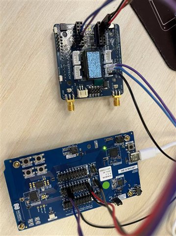
  • nRF54L15-DK. PCA10156
  • OLED SSD1306 128x64.
Software:
  • ncs v3.0.1
  •  Refer to zephyr/samples/subsys/display/lvgl.
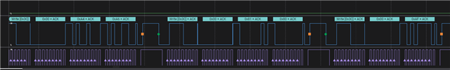
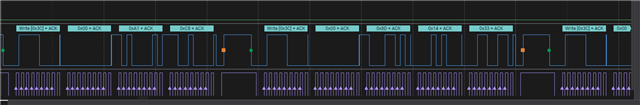
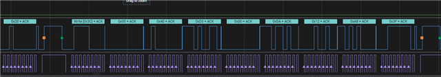
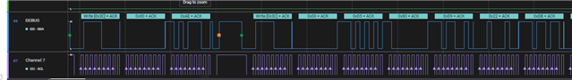
The attached file - hello_world.7z, was my testing code. I also attached some screenshots of the Logic analyzer for I2C data.
My questions:
  • I don't know why the display screen arose a snowflake screen.
  • Do you know what the LVGL is related to sdd1306?
BTW: 
In order to use the shield_ssd1306 from official sources, I temporarily added  "arduino_i2c: &i2c21 {};" in the zephyr/boards/nordic/nrf54l15dk/nrf54l15dk_nrf54l15_cpuapp.dts.
If you know other way without changing it, let me know.
Attachments:
Parents
  • Hello,

    I have seen that you have commented out the  SSD1306 device node from your overlay file, that is because you have used arduino shield. You have to add the shield in the device tree overlay file under the i2c1 node like following way (pointing this arduino_i2c: &i2c21 {};)

    &i2c21 {
        compatible = "nordic,nrf-twim";
        status = "okay";
        clock-frequency = <I2C_BITRATE_STANDARD>;
        zephyr,concat-buf-size = <4096>;
        pinctrl-0 = <&i2c21_default>;
        pinctrl-1 = <&i2c21_sleep>;
        pinctrl-names = "default", "sleep";
    };
    
    arduino_i2c: &i2c21 {};
    
    &pinctrl {
        i2c21_default: i2c21_default {
            group1 {
                psels = <NRF_PSEL(TWIM_SDA, 1, 11)>,
                        <NRF_PSEL(TWIM_SCL, 1, 12)>;
                bias-pull-up;
            };
        };
    
        i2c21_sleep: i2c21_sleep {
            group1 {
                psels = <NRF_PSEL(TWIM_SDA, 1, 11)>,
                        <NRF_PSEL(TWIM_SCL, 1, 12)>;
                low-power-enable;
            };
        };
    };

    In the prj.conf file, you should not coment out

    CONFIG_SSD1306=y and CONFIG_I2C=y.

Reply
  • Hello,

    I have seen that you have commented out the  SSD1306 device node from your overlay file, that is because you have used arduino shield. You have to add the shield in the device tree overlay file under the i2c1 node like following way (pointing this arduino_i2c: &i2c21 {};)

    &i2c21 {
        compatible = "nordic,nrf-twim";
        status = "okay";
        clock-frequency = <I2C_BITRATE_STANDARD>;
        zephyr,concat-buf-size = <4096>;
        pinctrl-0 = <&i2c21_default>;
        pinctrl-1 = <&i2c21_sleep>;
        pinctrl-names = "default", "sleep";
    };
    
    arduino_i2c: &i2c21 {};
    
    &pinctrl {
        i2c21_default: i2c21_default {
            group1 {
                psels = <NRF_PSEL(TWIM_SDA, 1, 11)>,
                        <NRF_PSEL(TWIM_SCL, 1, 12)>;
                bias-pull-up;
            };
        };
    
        i2c21_sleep: i2c21_sleep {
            group1 {
                psels = <NRF_PSEL(TWIM_SDA, 1, 11)>,
                        <NRF_PSEL(TWIM_SCL, 1, 12)>;
                low-power-enable;
            };
        };
    };

    In the prj.conf file, you should not coment out

    CONFIG_SSD1306=y and CONFIG_I2C=y.

Children
No Data
Related