Incorrect output from nPM1300 when powered through VBUS

Hi there,

I've designed a custom board implementing the nPM1300 and am currently in the process of examining the board without any firmware. Throughout testing, I have tried to power on the board using VBUS and VBAT.

The issue I am facing is:

- The output of VSYS and VOUT1/VOUT2 are correct when powering directly through VBAT using a power supply set at 3.7V. The current draw of the system sits at around 30 mA.

- The output of VSYS is incorrect (approx. 2V) when powered directly through VBUS using a power supply set at 5V. The current draw of the system is 0-0.5 mA.

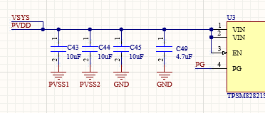
- This causes the output of VOUT1/VOUT2 and an external buck regulator that I have connected to VSYS to be incorrect.

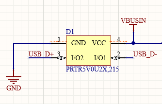
- The only additional connection to VBUS apart from the nPM1300 VBUS input is an ESD protection diode.

- I have also tried powering through VBUS using a USB cable connected to a power bank and laptop. When using the power bank, it delivers 5.15V into VBUS for around 20 seconds before dropping to around 2V.

Is this a hardware or firmware issue? I understand that there are some functions that can only be programmed through firmware, however I was under the assumption that the buck regulators and basic functionality (including being powered through VBUS) were possible without any firmware commands.

Thank you!

Parents
  • Hi

    With USB (VBUS), nPM1300 limits current to 100 mA by default. Without proper CC1/CC2 connections or firmware to raise the limit, nPM1300 SYSREG block can shut down under load, potentially even short inrush current spikes at startup can trigger this causing VSYS to drop to ~2 V.

    Regards 

    Tharaka

  • Hi Tharaka,

    I tried to limit my PSU to < 100 mA when powering directly through VBUS to see if transient current spikes were an issue but the issue remained. I was also under the impression that the nPM1300 could be powered directly through VBUS without CC negotiation, however it is connected to the USB-C port and seemed to work as intended with my laptop USB.

    I did notice as I was probing voltages however that when I accidentally shorted VBUS and VSYS that the all of the outputs and bucks would turn on with the correct voltages, and current draw went up to 30mA as expected. I know that this is probably not recommended, but what could be the reason why everything works properly after that?

  • Hi

    Thanks for the information.

    It looks like you have pre-charged your VSYS capacitors, bypassing the controlled startup sequence by shorting the VBUS and VSYS momentarily.This may have allowed the system to start without hitting current limits.

    During startup, SYSREG charges VSYS with a 100mA limit until it reaches ~2.9V, then the buck regulators turn on. If you have too much capacitance on the BUCK outputs or VSYS, the resulting inrush current exceeds the 100mA limit and causes VSYS to collapse.

    To find the root cause, 

    What is the total capacitance values at the pins VOUT1 and VOUT2? 
    Also the capacitance at the pins VSYS & PVDD?

    Or a screenshot of the schematic ?

    You can also try to isolate the issue, 

    • Disable both DCDCs: Ground VSET1 and VSET2 pins, then power via VBUS - does VSYS reach 5V properly?
    • Test one DCDC at a time: Enable only VOUT1 first, then only VOUT2, to see if one channel has excessive loading or if both are problematic individually.


    Also clarification needed:

    - I have also tried powering through VBUS using a USB cable connected to a power bank and laptop. When using the power bank, it delivers 5.15V into VBUS for around 20 seconds before dropping to around 2V.


    In your description, you mention VSYS drops to ~2V - can you confirm if it's VSYS or VBUS that collapses to 2V when the issue occurs?

    Regards 

    Tharaka 

Reply
  • Hi

    Thanks for the information.

    It looks like you have pre-charged your VSYS capacitors, bypassing the controlled startup sequence by shorting the VBUS and VSYS momentarily.This may have allowed the system to start without hitting current limits.

    During startup, SYSREG charges VSYS with a 100mA limit until it reaches ~2.9V, then the buck regulators turn on. If you have too much capacitance on the BUCK outputs or VSYS, the resulting inrush current exceeds the 100mA limit and causes VSYS to collapse.

    To find the root cause, 

    What is the total capacitance values at the pins VOUT1 and VOUT2? 
    Also the capacitance at the pins VSYS & PVDD?

    Or a screenshot of the schematic ?

    You can also try to isolate the issue, 

    • Disable both DCDCs: Ground VSET1 and VSET2 pins, then power via VBUS - does VSYS reach 5V properly?
    • Test one DCDC at a time: Enable only VOUT1 first, then only VOUT2, to see if one channel has excessive loading or if both are problematic individually.


    Also clarification needed:

    - I have also tried powering through VBUS using a USB cable connected to a power bank and laptop. When using the power bank, it delivers 5.15V into VBUS for around 20 seconds before dropping to around 2V.


    In your description, you mention VSYS drops to ~2V - can you confirm if it's VSYS or VBUS that collapses to 2V when the issue occurs?

    Regards 

    Tharaka 

Children
  • Hi Tharaka,

    After doing some testing today, I've found the following:

    - It turns out VBUS is the one collapsing from 5.15 V to around 2 V after approx. 20 seconds. When powered by VBUS, VSYS starts at around 2V while VBUS sits at 5.15V and then begins to decay once VBUS collapses.

    - I tried to short the VSET1 and VSET2 resistors using tweezers on start-up, however there was no change to the VBUS/VSYS behaviour.

    - I tried powering through VBUS and then shorting VBUS and VSYS to bypass the regulator to charge up the capacitors. From there, I tried turning off and then turning on the PSU quickly to see if it still worked afterwards. It did not.

    - I've attached a screenshot of the schematic below. The three 10uF capacitors were implemented similar to the application example. However, I did add an additional 4.7uF capacitor to VSYS for an external buck regulator connected to the VSYS rail. Could it be this addition that is adding too much capacitance to VSYS?

    - The capacitance at VOUT1 and 2 are 10uF.

    Thank you!

Related