About Tx current consumption in nRF54L

Hi,

I am currently developing an nRF54L15 module.

During the evaluation, I measured the Tx current consumption and got a result that was 2mA higher than the value listed in the data sheet.

The current consumption being confirmed is IRADIO_TX2 below.

Under the IRADIO_RX0 conditions, values ​​equivalent to those in the data sheet were measured.

To identify the cause, I modified it with an nRF54l dk and tried to measure at 3.0 V to see if there was a difference.
However, since it was impossible to measure at 3.0 V, I checked at 1.8 V to see if there was a current difference between the evaluation board and the module under development.


There was no difference in the results.
It was about 21mA.
When powered at 1.8V, the current consumption is the same as that of the nRF54L15, so I believe there will be no problems with the module under development.

The conditions for measurement at 1.8V were as follows:

Frequency: 2440MHz

Regulator: DC/DC

Tx Power: 8dBm

Modulation: BLE 1M

Firmware used:radio test sample code

sdk:v2.9.1


Measurements were also taken under the same conditions at 3.0V.


The current consumption of the nRF54ldk was measured using the diagram at the following URL as a reference.
docs.nordicsemi.com/.../measure_ampmeter.html

Please investigate what the problem is.

best regards,

Hiroki

  • Hello Hiroki,

    H-ogawa said:
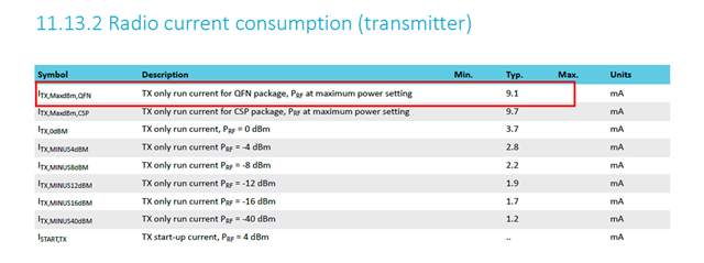
    When measured with Nordic's dedicated board, it is 9.1mA, but the Tx 8dBm listed in the data sheet below is 9.8mA. Why is there a difference?

    Can you please tell which version of datasheet you are mentioning here? This is not documented in the current datasheet.

  • Hi, Kazi

    The data sheet at the following URL is used as reference. This is v0.9.

    Is this version up to date?

    https://docs.nordicsemi.com/bundle/ps_nrf54L15/page/keyfeatures_html5.html

    It is understood that the following values ​​are measured on Nordic's internal board.

    The following values ​​are typical values ​​measured under the conditions described in 11.1.1 Conditions.

    I don't understand why there is a difference in the above in the first place, so I would like an explanation.

    Also, the module we developed is far from the typ in 11.1.2.5, so could you tell me what you think the cause could be?

    PS
    The Rx and Sleep values ​​for the module we developed are close to the typ in the data sheet.

    best regards,

    Hiroki

  • Hi,Kazi

    In order to quickly identify the cause of the problem, we modified the DK so that 3.0V was applied only to the nRF54l15.

    As a result, the current consumption during transmission changed depending on the nRF54l15dk's pattern antenna state.

    With pattern A, the current consumption was 12 mA.


    With pattern B, the current consumption was 9.8 mA, approaching the typical value on the data sheet.

    Also, the current consumption changes when I touch the pattern antenna.

    What causes this change in current consumption?

    best regards,

    Hiroki

  • Hello,

    "Also, the current consumption changes when I touch the pattern antenna.

    What causes this change in current consumption?"

    The antenna impedance will change when you touch it. A lower impedance will increase the current. The datasheet numbers are measured with a 50 ohm load on the antenna port. A "real" antenna will not always be 50 ohm so the current may differ.


  • Hi,Kazi

    The antenna impedance will change when you touch it. A lower impedance will increase the current. The datasheet numbers are measured with a 50 ohm load on the antenna port. A "real" antenna will not always be 50 ohm so the current may differ.

    Thank you for your comment.

    Why does the current consumption change when the impedance changes? Is it because the nRF54l15 has a function to automatically adjust the wireless output value?

    best regards,

    Hiroki

Related