Hello,
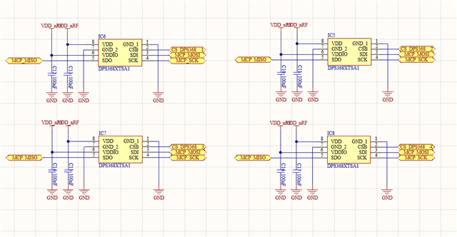
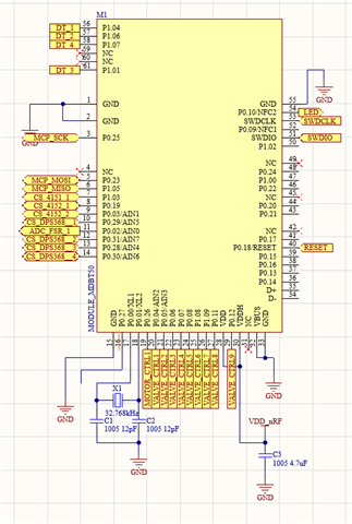
I am trying to use the DPS368XTSA1 sensor with the nRF52833 via SPI.
First, I’m attempting to read the sensor’s ID during initialization, but it’s not being read properly.
Could you help identify what might be wrong?
When executing the dps_init() function from main, a read command is sent to register 0x0D, which should return the PRODUCT ID 0x10, but no valid response is received.
const uint8_t dps_cs_pin[DPS368_NUM] = {
    CS_DPS368_1,
    CS_DPS368_2,
    CS_DPS368_3,
    CS_DPS368_4
};

static void spi_init(void)
{
    nrf_drv_spi_config_t spi_config = NRF_DRV_SPI_DEFAULT_CONFIG;
    spi_config.ss_pin   = NRF_DRV_SPI_PIN_NOT_USED;
    spi_config.miso_pin = MCP_MISO;
    spi_config.mosi_pin = MCP_MOSI;
    spi_config.sck_pin  = MCP_SCK;
    spi_config.frequency = NRF_DRV_SPI_FREQ_8M;
    spi_config.mode = NRF_DRV_SPI_MODE_3;

    //APP_ERROR_CHECK(nrf_drv_spi_init(&spi, &spi_config, spi_event_handler, NULL));
    ret_code_t err = nrf_drv_spi_init(&spi, &spi_config, spi_event_handler, NULL);

    //NRF_LOG_INFO("SPI INIT result: %d", err);NRF_LOG_FLUSH();
    if (err != NRF_SUCCESS) {
        NRF_LOG_ERROR("SPI INIT FAILED: %d", err);NRF_LOG_FLUSH();
        APP_ERROR_HANDLER(err);
    }
}

void sensor_select(uint8_t idx) {
    for (int i = 0; i < DPS368_NUM; i++) {
        nrf_gpio_pin_write(dps_cs_pin[i], 1);
    }
    nrf_gpio_pin_write(dps_cs_pin[idx], 0);
}

void sensor_deselect_all(void) {
    for (int i = 0; i < DPS368_NUM; i++) {
        nrf_gpio_pin_write(dps_cs_pin[i], 1);
    }
}

ret_code_t spi_read8(uint8_t sensor_idx, uint8_t reg, uint8_t* value) {
    sensor_select(sensor_idx);
    spi_xfer_done = false;

    m_tx_buf[0] = reg | 0x80; // Read bit
    m_tx_buf[1] = 0x00;       // Dummy byte

    spi_xfer_done = false;
    ret_code_t err = nrf_drv_spi_transfer(&spi, m_tx_buf, 2, m_rx_buf, 8);
    while (!spi_xfer_done)
    {
        __WFE();
    }

    *value = m_rx_buf[1];
    sensor_deselect_all();

    if (err != NRF_SUCCESS) {
        NRF_LOG_ERROR("spi_read8 failed: reg=0x%02X", reg);
    } else {
        NRF_LOG_INFO("spi_read8: reg=0x%02X → 0x%02X", reg, *value);
    }

    return err;
}

bool dps_init(uint8_t idx) {
    ret_code_t err;

    uint8_t product_id = 0;
    err = spi_read8(idx, 0x0D, &product_id);  // 0x0D: PRODUCT ID 레지스터 (read-only)
    if (err != NRF_SUCCESS) {
        NRF_LOG_ERROR("Sensor[%d] ID read failed", idx);
        return false;
    }
    NRF_LOG_INFO("Sensor[%d] ID: 0x%02X", idx, product_id);

    if (product_id != 0x10) {
        NRF_LOG_ERROR("Sensor[%d] Invalid PRODUCT ID: 0x%02X (expected 0x10)", idx, product_id);
        return false;
    }

    uint8_t revision_id = 0;
    err = spi_read8(idx, 0x0F, &revision_id);  // 0x0F: REV_ID 레지스터
    if (err != NRF_SUCCESS) {
        NRF_LOG_ERROR("Sensor[%d] REV_ID read failed", idx);
        return false;
    }
    NRF_LOG_INFO("Sensor[%d] REV_ID: 0x%02X", idx, revision_id);

    err = spi_write8(idx, 0x06, 0x04);  // PRS_CFG: pressure oversampling (PM_RATE=1, PM_PRC=4x)
    if (err != NRF_SUCCESS) {
        NRF_LOG_ERROR("Sensor[%d] PRS_CFG write failed", idx);
        return false;
    }

    err = spi_write8(idx, 0x07, 0x04);  // TMP_CFG: temperature oversampling (TMP_RATE=1, TMP_PRC=4x)
    if (err != NRF_SUCCESS) {
        NRF_LOG_ERROR("Sensor[%d] TMP_CFG write failed", idx);
        return false;
    }

    err = spi_write8(idx, 0x09, 0x0C);  // CFG_REG: INT_SEL=0, shift enabled (bit3=1, bit2=1)
    if (err != NRF_SUCCESS) {
        NRF_LOG_ERROR("Sensor[%d] CFG_REG write failed", idx);
        return false;
    }

    err = spi_write8(idx, 0x08, 0x07);  // MEAS_CFG: start continuous pressure + temperature
    if (err != NRF_SUCCESS) {
        NRF_LOG_ERROR("Sensor[%d] MEAS_CFG write failed", idx);
        return false;
    }

    nrf_delay_ms(50);
    NRF_LOG_INFO("Sensor[%d] measurement started", idx);
    return true;
}


int main(void)
{
    //bool erase_bonds;
    uint32_t err_code;
    ret_code_t ret;

    log_init();

    timers_init();
    gpio_init();

    clock_init();
    power_management_init();
    set_dcdc_3v0();

    ble_stack_init();
    gap_params_init();
    gatt_init();
    services_init();
    advertising_init();
    conn_params_init();

    //SAADC
    saadc_init();
    saadc_sampling_event_init();
    saadc_sampling_event_enable();

    // DPS368 init
    spi_init();

    // Enter main loop.
    for (;;)
    {
        NRF_LOG_FLUSH();
	idle_state_handle();

        if(imsi_init_flag == false) {
        //SPI_SEND(Air_Offset, 0x10, 2);
            NRF_LOG_INFO("------------------------------------00");NRF_LOG_FLUSH();
            imsi_init_flag = true;
            for (int i = 0; i < DPS368_NUM; i++) {
                if (!dps_init(i)) {
                    NRF_LOG_INFO("Sensor %d init failed", i);NRF_LOG_FLUSH();
                }
            }
        }