I think I broke my bootloader, looking for help.

So I got me one of these

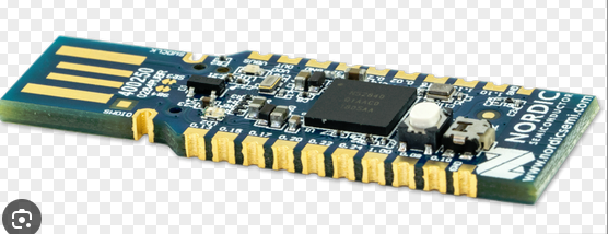
and after a day of making it work on windows I was able to lunch visual code from wsl and compile. the next day I found how to make a flash with nrfutil and was able to create a zip. So I pressed the button and the LED changed its blink rate, and I ran a few commands.

nrfutil keys generate private.key       

nrfutil pkg generate --hw-version 52 --sd-req 0x00 --application nrf52832_xxaa.hex --application-version 1 --key-file private.key app_dfu_package.zip    

nrfutil dfu serial -p COM5 -pkg app_dfu_package.zip -b 115200

I then got this

  [####################################]  100%
Device programmed.

now the device is dead. I tried holding down the button on insert and pressing after it was in. no USB chine no led. I flashed the gpiote example in hopes it woudl be a BT device that used GPIO pins, but it just make a brick.

Can this be fixed? If not, what did I do wrong?

Parents Reply
  • You can solder a 10 pin header to the bottom of the dongle, then connect to an external debugger.

    For most development work I'd recommend a full development kit, it's not a great experience to use the dongle and use serial DFU vs. a full debugger.

    My guess is that the bootloader fails to use an image with your own keys and dies before executing the application.

Children
  • I have a full dev kit, I just need to know how to make the dongle work as my device will also use that.

    DFU is not new, this is a hugely common way to update firmware, why does everyone keep dodging the question, on here, in email, online... DFU is for the user experience why is this so difficult?

    Yes, I have a dev board, that is not my issue.I need to know how to flash the DFU  correctly and how to recover it ( this should not even be happening).  Guessing 1,2,3,4,5 down 6,7,8,9,10 up, and this is a j-tag? the dev board (nRF52840 ) has no 10 pin header I can find.

    Can I download a key that works with the bootloader? the firmware creation required I make one.

    I have the 10 pin on the bottom, but I'd need some type of wiring guide to show what I need to solder it to. Guessing it connects to my dev board (somehow.

    Normally, at least in my experience, you make a device, with a dev kit, then you make a boot loader for updates. The user has software to update it. That boot loader and software need to be nearly rock solid, because no one wants to spent time repairing a device they bought. So far the boot loader seem to be the hardest part of all of this. I'm thinking maybe I have misunderstood something here but I'm not sure.


  • It's impossible to tell you what is wrong with the bootloader since you cannot get logs out of it on the dongle. If boot fails, no logs come through the USB-CDC ACM port. That's why my recommendation is to use a development kit to diagnose these issues, building for an nRF52840-DK target before moving to the dongle. You also appear to have flashed an nRF52832 image to an nRF52840 dongle. 

    "nrfutil pkg generate --hw-version 52 --sd-req 0x00 --application nrf52832_xxaa.hex --application-version 1 --key-file private.key app_dfu_package.zip"

    Here is info on how to access the SWD pins on the dongle where it can be flashed with an MCUboot enabled application:

    https://docs.nordicsemi.com/bundle/ug_nrf52840_dongle/page/UG/nrf52840_Dongle/hw_swd_if.html

    For more information on adding MCUboot serial DFU to an application:

    academy.nordicsemi.com/.../

  • I think Chat GPT explained it best. This is not a dongle I can use its just junk to evaluate. So I need to some how program my boot loader to this via the 10 pin connector. Or manually solder on the chip ( hope not) to test how this will work for a user experience


    Also I think I can just make this connection to program the bootloader with my keys

    • DK P19 SWDIO → Dongle SWDIO

    • DK P19 SWDCLK → Dongle SWDCLK

    • DK P19 GND → Dongle GND

    • DK P19 VCC → Dongle VCC 

Related