SPI not working with AFE4490 sensor

Hello community,

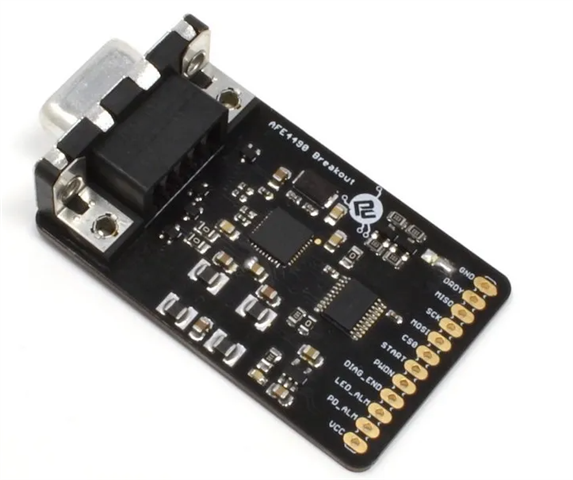
I have been recently working with AFE4490 sensor from protocentral (breakout board).

GitHub - Protocentral/protocentral-afe4490-arduino: Arduino Library for the AFE4490 SPO2 shield and breakout boards from Protocentral

Previously I have ported multiple sensors for my hobby projects and never faced any issue but I am not able to initialize the registers with this sensor in nrf52840.

Here are few things I trieD:

1. I evaluated this sensor with ESP32 C3 module and the sensor LED turns ON after succesful intialization.

2. Ported the C++ code base to nrf52840 SPI peripheral example code and description is mentioned below:

3. Used SPI pin as mentioned below:

#define AFE_MISO_PIN 30//24
#define AFE_MOSI_PIN 29//23
#define AFE_SCK_PIN 28//25
#define AFE_CS_Pin 31//22

4. Initialization routine for SPI is mentioned below:

nrf_drv_spi_config_t spi_config = NRF_DRV_SPI_DEFAULT_CONFIG;
spi_config.miso_pin = AFE_MISO_PIN;
spi_config.mosi_pin = AFE_MOSI_PIN;
spi_config.sck_pin = AFE_SCK_PIN;
spi_config.ss_pin = AFE_CS_Pin;
spi_config.mode = NRF_DRV_SPI_MODE_1;
spi_config.frequency = NRF_DRV_SPI_FREQ_8M;
//spi_config.irq_priority = APP_IRQ_PRIORITY_HIGH;
//spi_config.orc = 0x54; // fla
APP_ERROR_CHECK(nrf_drv_spi_init(&afe_spi, &spi_config, afe_spi_event_handler, NULL));

nrf_gpio_cfg_output(AFE_MOSI_PIN);
nrf_gpio_cfg_output(AFE_SCK_PIN);
nrf_gpio_cfg_output(AFE_CS_Pin);

nrf_gpio_cfg_output(NRF_GPIO_PIN_MAP(1,11)); //This is for power down pin in AFE4490, used to reset it by toggling GPIO before initialization of registers.

nrf_delay_ms(300);

5. Register initialization is mentioned below: (Taken from working example code of ESP32 - Attached link to it in the above section)

nrf_gpio_pin_clear(NRF_GPIO_PIN_MAP(1,11));
nrf_delay_ms(100);
nrf_gpio_pin_set(NRF_GPIO_PIN_MAP(1,11));
nrf_delay_ms(60);

//nrf_gpio_pin_toggle(NRF_GPIO_PIN_MAP(1,11));

////Example code
//DisableSPIRead();
afe44xxWrite(CONTROL0, 0x000000);
afe44xxWrite(CONTROL0, 0x000008);
afe44xxWrite(TIAGAIN, 0x000000); // CF = 5pF, RF = 500kR
afe44xxWrite(TIA_AMB_GAIN, 0x000001);
afe44xxWrite(LEDCNTRL, 0x001414);
afe44xxWrite(CONTROL2, 0x000000); // LED_RANGE=100mA, LED=50mA
afe44xxWrite(CONTROL1, 0x010707); // Timers ON, average 3 samples
afe44xxWrite(PRPCOUNT, 0X001F3F);
afe44xxWrite(LED2STC, 0X001770);
afe44xxWrite(LED2ENDC, 0X001F3E);
afe44xxWrite(LED2LEDSTC, 0X001770);
afe44xxWrite(LED2LEDENDC, 0X001F3F);
afe44xxWrite(ALED2STC, 0X000000);
afe44xxWrite(ALED2ENDC, 0X0007CE);
afe44xxWrite(LED2CONVST, 0X000002);
afe44xxWrite(LED2CONVEND, 0X0007CF);
afe44xxWrite(ALED2CONVST, 0X0007D2);
afe44xxWrite(ALED2CONVEND, 0X000F9F);
afe44xxWrite(LED1STC, 0X0007D0);
afe44xxWrite(LED1ENDC, 0X000F9E);
afe44xxWrite(LED1LEDSTC, 0X0007D0);
afe44xxWrite(LED1LEDENDC, 0X000F9F);
afe44xxWrite(ALED1STC, 0X000FA0);
afe44xxWrite(ALED1ENDC, 0X00176E);
afe44xxWrite(LED1CONVST, 0X000FA2);
afe44xxWrite(LED1CONVEND, 0X00176F);
afe44xxWrite(ALED1CONVST, 0X001772);
afe44xxWrite(ALED1CONVEND, 0X001F3F);
afe44xxWrite(ADCRSTCNT0, 0X000000);
afe44xxWrite(ADCRSTENDCT0, 0X000000);
afe44xxWrite(ADCRSTCNT1, 0X0007D0);
afe44xxWrite(ADCRSTENDCT1, 0X0007D0);
afe44xxWrite(ADCRSTCNT2, 0X000FA0);
afe44xxWrite(ADCRSTENDCT2, 0X000FA0);
afe44xxWrite(ADCRSTCNT3, 0X001770);
afe44xxWrite(ADCRSTENDCT3, 0X001770);

6. Ported write function is mentioned below:

uint8_t usTxAfeCmdWrite[30];
void afe44xxWrite (uint8_t address, uint32_t data)
{
memset(usTxAfeCmdWrite, 0 ,30);
usTxAfeCmdWrite[0] = address;
usTxAfeCmdWrite[1] = ((data >> 16) & 0xFF);
usTxAfeCmdWrite[2] = ((data >> 8) & 0xFF);
usTxAfeCmdWrite[3] = (data & 0xFF);

CS_OFF;
nrf_drv_spi_transfer(&afe_spi, usTxAfeCmdWrite, 4, 0, 0);
while (!AfebXferDone);  //This will be true in the spi_handler function - basically the spi event check callback.
CS_ON;

}

Original working Arduino write function mentioned below:

void AFE44XX :: afe44xxWrite (uint8_t address, uint32_t data)
{
SPI.beginTransaction(SPI_SETTINGS);
digitalWrite (_cs_pin, LOW); // enable device
SPI.transfer (address); // send address to device
SPI.transfer ((data >> 16) & 0xFF); // write top 8 bits
SPI.transfer ((data >> 8) & 0xFF); // write middle 8 bits
SPI.transfer (data & 0xFF); // write bottom 8 bits
digitalWrite (_cs_pin, HIGH); // disable device
SPI.endTransaction();
}

Currently, I am more focused on register initialiozation. Once its success then I will proceed further with reading of SPo2 and heart rate values. 

I am not sure where I am going wrong, I tried changing the modes to Mode 0,1,2,3 but nothing works. Its been a week now. Requesting somebody to help me on this.

Thank you.

  • #include "AFE4490.h"
    #include "stdint.h"
    #include "AFE4490_SPO2_Algo.h"
    #include "AFE4490_HR_Algo.h"
    #include "nrf_delay.h"
    #include "nrf_gpio.h"
    //#define AFE44XX_SPI_SPEED 2000000
    //SPISettings SPI_SETTINGS(AFE44XX_SPI_SPEED, MSBFIRST, SPI_MODE0); 
    
    //afe44xx Register definition
    #define CONTROL0      0x00
    #define LED2STC       0x01
    #define LED2ENDC      0x02
    #define LED2LEDSTC    0x03
    #define LED2LEDENDC   0x04
    #define ALED2STC      0x05
    #define ALED2ENDC     0x06
    #define LED1STC       0x07
    #define LED1ENDC      0x08
    #define LED1LEDSTC    0x09
    #define LED1LEDENDC   0x0a
    #define ALED1STC      0x0b
    #define ALED1ENDC     0x0c
    #define LED2CONVST    0x0d
    #define LED2CONVEND   0x0e
    #define ALED2CONVST   0x0f
    #define ALED2CONVEND  0x10
    #define LED1CONVST    0x11
    #define LED1CONVEND   0x12
    #define ALED1CONVST   0x13
    #define ALED1CONVEND  0x14
    #define ADCRSTCNT0    0x15
    #define ADCRSTENDCT0  0x16
    #define ADCRSTCNT1    0x17
    #define ADCRSTENDCT1  0x18
    #define ADCRSTCNT2    0x19
    #define ADCRSTENDCT2  0x1a
    #define ADCRSTCNT3    0x1b
    #define ADCRSTENDCT3  0x1c
    #define PRPCOUNT      0x1d
    #define CONTROL1      0x1e
    #define SPARE1        0x1f
    #define TIAGAIN       0x20
    #define TIA_AMB_GAIN  0x21
    #define LEDCNTRL      0x22
    #define CONTROL2      0x23
    #define SPARE2        0x24
    #define SPARE3        0x25
    #define SPARE4        0x26
    #define SPARE4        0x26
    #define RESERVED1     0x27
    #define RESERVED2     0x28
    #define ALARM         0x29
    #define LED2VAL       0x2a
    #define ALED2VAL      0x2b
    #define LED1VAL       0x2c
    #define ALED1VAL      0x2d
    #define LED2ABSVAL    0x2e
    #define LED1ABSVAL    0x2f
    #define DIAG          0x30
    
    #define SPI_INSTANCE  0 /**< SPI instance index. */
    static const nrf_drv_spi_t spi = NRF_DRV_SPI_INSTANCE(SPI_INSTANCE);  /**< SPI instance. */
    
    volatile bool afe44xx_data_ready = false;
    volatile int8_t n_buffer_count; //data length
    
    int dec=0;
    
    unsigned long IRtemp,REDtemp;
    
    int32_t n_spo2;  //SPO2 value
    int32_t n_heart_rate; //heart rate value
    
    uint16_t aun_ir_buffer[100]; //infrared LED sensor data
    uint16_t aun_red_buffer[100];  //red LED sensor data
    
    int8_t ch_spo2_valid;  //indicator to show if the SPO2 calculation is valid
    int8_t  ch_hr_valid;  //indicator to show if the heart rate calculation is valid
    
    //const uint8_t uch_spo2_table[184]={ 95, 95, 95, 96, 96, 96, 97, 97, 97, 97, 97, 98, 98, 98, 98, 98, 99, 99, 99, 99,
    //                                    99, 99, 99, 99, 100, 100, 100, 100, 100, 100, 100, 100, 100, 100, 100, 100, 100, 100, 100, 100,
    //                                   100, 100, 100, 100, 99, 99, 99, 99, 99, 99, 99, 99, 98, 98, 98, 98, 98, 98, 97, 97,
    //                                    97, 97, 96, 96, 96, 96, 95, 95, 95, 94, 94, 94, 93, 93, 93, 92, 92, 92, 91, 91,
    //                                    90, 90, 89, 89, 89, 88, 88, 87, 87, 86, 86, 85, 85, 84, 84, 83, 82, 82, 81, 81,
    //                                    80, 80, 79, 78, 78, 77, 76, 76, 75, 74, 74, 73, 72, 72, 71, 70, 69, 69, 68, 67,
    //                                    66, 66, 65, 64, 63, 62, 62, 61, 60, 59, 58, 57, 56, 56, 55, 54, 53, 52, 51, 50,
    //                                    49, 48, 47, 46, 45, 44, 43, 42, 41, 40, 39, 38, 37, 36, 35, 34, 33, 31, 30, 29,
    //                                    28, 27, 26, 25, 23, 22, 21, 20, 19, 17, 16, 15, 14, 12, 11, 10, 9, 7, 6, 5,
    //                                    3,   2,  1  } ;
    
    #define CS_ON               nrf_gpio_pin_set( AFE_CS_Pin )
    #define CS_OFF              nrf_gpio_pin_clear( AFE_CS_Pin )
    
    #define AFE_MISO_PIN        30//24
    #define AFE_MOSI_PIN        29//23
    #define AFE_SCK_PIN         28//25
    #define AFE_CS_Pin          31//22
    
    //#define SPI
    #define SPIM
    
    #ifdef SPI
    #define SPI_INSTANCE 0                                                   // SPI instance index.
    static const nrf_drv_spi_t afe_spi = NRF_DRV_SPI_INSTANCE(SPI_INSTANCE); // SPI instance.
    #endif
    
    #ifdef SPIM
    #define SPIM_INSTANCE 0                                                 // SPI instance index.
    static const nrfx_spim_t lcd_spim = NRFX_SPIM_INSTANCE(SPIM_INSTANCE); // SPI instance.
    static uint8_t m_tx_buf[] = {0xff, 0xff, 0xff};                        // TX buffer.
    nrfx_spim_xfer_desc_t xfer_desc;
    #endif
    
    #define _pwdn_pin  NRF_GPIO_PIN_MAP(1,15)
    
    int _drdy_pin;
    volatile bool AfebXferDone = false;
    
    uint8_t SPI_ReadWriteByte(uint8_t TxData );
    void AFE_spi_tx(uint8_t *data, size_t len);
    void AFE_write_data(uint8_t *data, size_t len);
    void AFE_write_command(uint8_t cmd);
    void afe44xxWrite (uint8_t address,uint32_t data);
    void DisableSPIRead(void);
    void EnableSPIRead(void);
    
    void afe_spi_event_handler(nrf_drv_spi_evt_t const * p_event,
    void *                    p_context)
    {
      switch( p_event->type ){
        case NRF_DRV_SPI_EVENT_DONE:
          AfebXferDone = true;
        break;
      }
    }
    
    void AFE44XX(void)
    {
        #ifdef SPI
        /* SPI */
        nrf_drv_spi_config_t spi_config = NRF_DRV_SPI_DEFAULT_CONFIG;
        spi_config.miso_pin = AFE_MISO_PIN;
        spi_config.mosi_pin = AFE_MOSI_PIN;
        spi_config.sck_pin = AFE_SCK_PIN;
        spi_config.ss_pin = AFE_CS_Pin;
        spi_config.mode = NRF_DRV_SPI_MODE_1;
        spi_config.frequency = NRF_DRV_SPI_FREQ_8M;
        //spi_config.irq_priority = APP_IRQ_PRIORITY_HIGH;
        //spi_config.orc = 0x54; // fla
        APP_ERROR_CHECK(nrf_drv_spi_init(&afe_spi, &spi_config, afe_spi_event_handler, NULL));
        #endif
    
        #ifdef SPIM
        /* SPIM */
        nrfx_spim_config_t spim_config = NRFX_SPIM_DEFAULT_CONFIG;
        spim_config.miso_pin = AFE_MISO_PIN;
        spim_config.mosi_pin = AFE_MOSI_PIN;
        spim_config.sck_pin = AFE_SCK_PIN;
        spim_config.ss_pin = AFE_CS_Pin;
        spim_config.frequency = NRF_SPIM_FREQ_8M;
        APP_ERROR_CHECK(nrfx_spim_init(&lcd_spim, &spim_config, NULL, NULL));
        #endif
    
        nrf_gpio_cfg_output(AFE_MOSI_PIN);
        nrf_gpio_cfg_output(AFE_SCK_PIN);
        nrf_gpio_cfg_output(AFE_CS_Pin);
    
        //nrf_gpio_pin_clear(AFE_SCK_PIN);
        //nrf_gpio_pin_clear(AFE_MOSI_PIN);
        nrf_gpio_pin_set(AFE_CS_Pin);
        //nrf_gpio_cfg_input(AFE_MISO_PIN,NRF_GPIO_PIN_PULLUP);
    
        nrf_gpio_cfg_output(NRF_GPIO_PIN_MAP(1,11));
    
        nrf_delay_ms(300);
    
        initStatHRM();
    }
    
    void AFE_write_command(uint8_t cmd) {
        CS_OFF;
    #ifdef SPIM
        xfer_desc.p_tx_buffer = &cmd;      // for SPIM
        xfer_desc.tx_length = sizeof(cmd); // for SPIM
    #endif
    #ifdef SPI
        AFE_spi_tx(&cmd, sizeof(cmd));
    #endif
        CS_ON;
    }
    
    void AFE_write_data(uint8_t *data, size_t len) {
        CS_OFF;
    #ifdef SPIM
        xfer_desc.p_tx_buffer = data; // for SPIM
        xfer_desc.tx_length = len;    // for SPIM
    #endif
    #ifdef SPI
        AFE_spi_tx(data, len);
    #endif
        CS_ON;
    }
    
    void AFE_spi_tx(uint8_t *data, size_t len) {
    #ifdef SPI
        nrf_drv_spi_transfer(&afe_spi, data, len, 0, 0);
        while (!AfebXferDone);
    #endif
    #ifdef SPIM
        nrfx_spim_xfer(&lcd_spim, &xfer_desc, 0); // for SPIM
    #endif
    }
    
    bool get_AFE44XX_Data(afe44xx_data *afe44xx_raw_data)
    {
      afe44xxWrite(CONTROL0, 0x000001);
      IRtemp = afe44xxRead(LED1VAL);
      afe44xxWrite(CONTROL0, 0x000001);
      REDtemp = afe44xxRead(LED2VAL);
      //afe44xxWrite(CONTROL0, 0x000001);
      //ulReadData = afe44xxRead(LEDCNTRL);
      afe44xx_data_ready = true;
      IRtemp = (unsigned long) (IRtemp << 10);
      afe44xx_raw_data->IR_data = (signed long) (IRtemp);
      afe44xx_raw_data->IR_data = (signed long) ((afe44xx_raw_data->IR_data) >> 10);
      REDtemp = (unsigned long) (REDtemp << 10);
      afe44xx_raw_data->RED_data = (signed long) (REDtemp);
      afe44xx_raw_data->RED_data = (signed long) ((afe44xx_raw_data->RED_data) >> 10);
    
      if (dec == 20)
      {
        aun_ir_buffer[n_buffer_count] = (uint16_t) ((afe44xx_raw_data->IR_data) >> 4);
        aun_red_buffer[n_buffer_count] = (uint16_t) ((afe44xx_raw_data->RED_data) >> 4);
        n_buffer_count++;
        dec = 0;
      }
    
      dec++;
    
      if (n_buffer_count > 99)
      {
        estimate_spo2(aun_ir_buffer, 100, aun_red_buffer, &n_spo2, &ch_spo2_valid, &n_heart_rate, &ch_hr_valid);
        afe44xx_raw_data->spo2 = n_spo2;
        //afe44xx_raw_data->heart_rate = n_heart_rate;
        n_buffer_count = 0;
        afe44xx_raw_data->buffer_count_overflow = true;
      }
    
      statHRMAlgo(afe44xx_raw_data->RED_data);
      afe44xx_raw_data->heart_rate = HeartRate;
    
      afe44xx_data_ready = false;
      return true;
    
    }
    
    uint32_t readdata;
    void afe44xx_init()
    {
      nrf_gpio_pin_clear(NRF_GPIO_PIN_MAP(1,11));
      nrf_delay_ms(100);
      nrf_gpio_pin_set(NRF_GPIO_PIN_MAP(1,11));
      nrf_delay_ms(60);
    
      //nrf_gpio_pin_toggle(NRF_GPIO_PIN_MAP(1,11));
    
      ////Example code
      //DisableSPIRead();
      afe44xxWrite(CONTROL0, 0x000000);
      afe44xxWrite(CONTROL0, 0x000008);
      afe44xxWrite(TIAGAIN, 0x000000); // CF = 5pF, RF = 500kR
      afe44xxWrite(TIA_AMB_GAIN, 0x000001);
      afe44xxWrite(LEDCNTRL, 0x001414);
      afe44xxWrite(CONTROL2, 0x000000); // LED_RANGE=100mA, LED=50mA
      afe44xxWrite(CONTROL1, 0x010707); // Timers ON, average 3 samples
      afe44xxWrite(PRPCOUNT, 0X001F3F);
      afe44xxWrite(LED2STC, 0X001770);
      afe44xxWrite(LED2ENDC, 0X001F3E);
      afe44xxWrite(LED2LEDSTC, 0X001770);
      afe44xxWrite(LED2LEDENDC, 0X001F3F);
      afe44xxWrite(ALED2STC, 0X000000);
      afe44xxWrite(ALED2ENDC, 0X0007CE);
      afe44xxWrite(LED2CONVST, 0X000002);
      afe44xxWrite(LED2CONVEND, 0X0007CF);
      afe44xxWrite(ALED2CONVST, 0X0007D2);
      afe44xxWrite(ALED2CONVEND, 0X000F9F);
      afe44xxWrite(LED1STC, 0X0007D0);
      afe44xxWrite(LED1ENDC, 0X000F9E);
      afe44xxWrite(LED1LEDSTC, 0X0007D0);
      afe44xxWrite(LED1LEDENDC, 0X000F9F);
      afe44xxWrite(ALED1STC, 0X000FA0);
      afe44xxWrite(ALED1ENDC, 0X00176E);
      afe44xxWrite(LED1CONVST, 0X000FA2);
      afe44xxWrite(LED1CONVEND, 0X00176F);
      afe44xxWrite(ALED1CONVST, 0X001772);
      afe44xxWrite(ALED1CONVEND, 0X001F3F);
      afe44xxWrite(ADCRSTCNT0, 0X000000);
      afe44xxWrite(ADCRSTENDCT0, 0X000000);
      afe44xxWrite(ADCRSTCNT1, 0X0007D0);
      afe44xxWrite(ADCRSTENDCT1, 0X0007D0);
      afe44xxWrite(ADCRSTCNT2, 0X000FA0);
      afe44xxWrite(ADCRSTENDCT2, 0X000FA0);
      afe44xxWrite(ADCRSTCNT3, 0X001770);
      afe44xxWrite(ADCRSTENDCT3, 0X001770);
      //EnableSPIRead();
      //readdata = afe44xxRead(LEDCNTRL);
      //__asm("NOP");
    
      //unsigned long ulReadData = afe44xxRead(ADCRSTENDCT3);
    
      ////Semi working
       //disable_afe4490_spi_read(afe4490); // Enable modification of AFE4490 registers
       #if 0 //to semi working code
      afe44xxWrite(CONTROL0,0x000002);
      afe44xxWrite(PRPCOUNT,0x001072);
      afe44xxWrite(CONTROL0,0x000000);  
      afe44xxWrite(CONTROL1, 0x000101);
      //DisableSPIRead();
      afe44xxWrite(LED2STC, 0x000CA4); //LED2STC
      afe44xxWrite(LED2ENDC, 0x00106E); //LED2ENDC
      afe44xxWrite(LED2LEDSTC, 0x000C54); //LED1LEDSTC
      afe44xxWrite(LED2LEDENDC,0x00106F); //LED1LEDENDC
      afe44xxWrite(ALED2STC, 0x000050); //ALED2STC
      afe44xxWrite(ALED2ENDC, 0x00041A); //ALED2ENDC
      afe44xxWrite(LED1STC, 0x00046C); //LED1STC
      afe44xxWrite(LED1ENDC, 0x000836); //LED1ENDC
      afe44xxWrite(LED1LEDSTC, 0x00041C); //LED2LEDSTC
      afe44xxWrite(LED1LEDENDC, 0x000837); //LED2LEDENDC
      afe44xxWrite(ALED1STC, 0x000888); //ALED1STC
      afe44xxWrite(ALED1ENDC, 0x000C52); //ALED1ENDC
      afe44xxWrite(LED2CONVST, 0x000006); //LED2CONVST
      afe44xxWrite(LED2CONVEND, 0x00041B); //LED2CONVEND
      afe44xxWrite(ALED2CONVST, 0x000422); //ALED2CONVST
      afe44xxWrite(ALED2CONVEND, 0x000837); //ALED2CONVEND
      afe44xxWrite(LED1CONVST, 0x00083E); //LED1CONVST
      afe44xxWrite(LED1CONVEND, 0x000C53); //LED1CONVEND
      afe44xxWrite(ALED1CONVST, 0x000C5A); //ALED1CONVST
      afe44xxWrite(ALED1CONVEND, 0x00106F); //ALED1CONVEND
      afe44xxWrite(ADCRSTCNT0, 0x000000); //ADCRSTSTCT0
      afe44xxWrite(ADCRSTENDCT0,0x000005); //ADCRSTENDCT0
      afe44xxWrite(ADCRSTCNT1, 0x00041C); //ADCRSTSTCT1
      afe44xxWrite(ADCRSTENDCT1, 0x000421); //ADCRSTENDCT1
      afe44xxWrite(ADCRSTCNT2, 0x000838); //ADCRSTSTCT2
      afe44xxWrite(ADCRSTENDCT2, 0x00083D); //ADCRSTENDCT2
      afe44xxWrite(ADCRSTCNT3, 0x000C54); //ADCRSTSTCT3
      afe44xxWrite(ADCRSTENDCT3, 0x000C59); //ADCRSTENDCT3
      afe44xxWrite(PRPCOUNT, 0x001072); //PRPCT 0x009C3F 0x00115B
      afe44xxWrite(CONTROL1, 0x000101); //CONTROL1
      afe44xxWrite(TIAGAIN, 0x000000); //TIA_GAIN
      afe44xxWrite(TIA_AMB_GAIN, 0x000000); //TIA_AMB_GAIN
      afe44xxWrite(LEDCNTRL, 0x014401); //LEDCTRL
      afe44xxWrite(CONTROL2, 0x000000); //CONTROL2 0x124218
      EnableSPIRead();
      #endif
      //unsigned long ReadValue1 = afe44xxRead(ALED1CONVEND);
      //unsigned long ReadValue2 = afe44xxRead(ALED2STC);
    
      //afe44xxWrite(CONTROL1, 0x000101);
      //afe44xxWrite(CONTROL2, 0x000000);
      //afe44xxWrite(PRPCOUNT, 0X001F3F);
      //afe44xxWrite(LED2STC, 0X001770); //timer control
      //afe44xxWrite(LED2ENDC,0X001F3E); //timer control
      //afe44xxWrite(LED2LEDSTC,0X001770); //timer control
      //afe44xxWrite(LED2LEDENDC,0X001F3F); //timer control
      //afe44xxWrite(ALED2STC, 0X000000); //timer control
      //afe44xxWrite(ALED2ENDC, 0X0007CE); //timer control
      //afe44xxWrite(LED2CONVST,0X000002); //timer control
      //afe44xxWrite(LED2CONVEND, 0X0007CF); //timer control
      //afe44xxWrite(ALED2CONVST, 0X0007D2); //timer control
      //afe44xxWrite(ALED2CONVEND,0X000F9F); //timer control
      //afe44xxWrite(LED1STC, 0X0007D0); //timer control
      //afe44xxWrite(LED1ENDC, 0X000F9E); //timer control
      //afe44xxWrite(LED1LEDSTC, 0X0007D0); //timer control
      //afe44xxWrite(LED1LEDENDC, 0X000F9F); //timer control
      //afe44xxWrite(ALED1STC, 0X000FA0); //timer control
      //afe44xxWrite(ALED1ENDC, 0X00176E); //timer control
      //afe44xxWrite(LED1CONVST, 0X000FA2); //timer control
      //afe44xxWrite(LED1CONVEND, 0X00176F); //timer control
      //afe44xxWrite(ALED1CONVST, 0X001772); //timer control
      //afe44xxWrite(ALED1CONVEND, 0X001F3F); //timer control
      //afe44xxWrite(ADCRSTCNT0, 0X000000); //timer control
      //afe44xxWrite(ADCRSTENDCT0,0X000000); //timer control
      //afe44xxWrite(ADCRSTCNT1, 0X0007D0); //timer control
      //afe44xxWrite(ADCRSTENDCT1, 0X0007D0); //timer control
      //afe44xxWrite(ADCRSTCNT2, 0X000FA0); //timer control
      //afe44xxWrite(ADCRSTENDCT2, 0X000FA0); //timer control
      //afe44xxWrite(ADCRSTCNT3, 0X001770); //timer control
      //afe44xxWrite(ADCRSTENDCT3, 0X001770);
      //afe44xxWrite(LEDCNTRL, 0x014401); //LEDCTRL
    
      //  afe44xxWrite(CONTROL0,0x000002);
      //afe44xxWrite(PRPCOUNT,0x001072);
      //afe44xxWrite(CONTROL0,0x000000);  
      //afe44xxWrite(CONTROL1, 0x000100);
      ////disable_afe4490_spi_read(afe4490); // Enable modification of AFE4490 registers
      //afe44xxWrite(LED2STC, 0x000CA4); //LED2STC
      //afe44xxWrite(LED2ENDC, 0x00106E); //LED2ENDC
      //afe44xxWrite(LED2LEDSTC, 0x000C54); //LED1LEDSTC
      //afe44xxWrite(LED2LEDENDC,0x00106F); //LED1LEDENDC
      //afe44xxWrite(ALED2STC, 0x000050); //ALED2STC
      //afe44xxWrite(ALED2ENDC, 0x00041A); //ALED2ENDC
      //afe44xxWrite(LED1STC, 0x00046C); //LED1STC
      //afe44xxWrite(LED1ENDC, 0x000836); //LED1ENDC
      //afe44xxWrite(LED1LEDSTC, 0x00041C); //LED2LEDSTC
      //afe44xxWrite(LED1LEDENDC, 0x000837); //LED2LEDENDC
      //afe44xxWrite(ALED1STC, 0x000888); //ALED1STC
      //afe44xxWrite(ALED1ENDC, 0x000C52); //ALED1ENDC
      //afe44xxWrite(LED2CONVST, 0x000006); //LED2CONVST
      //afe44xxWrite(LED2CONVEND, 0x00041B); //LED2CONVEND
      //afe44xxWrite(ALED2CONVST, 0x000422); //ALED2CONVST
      //afe44xxWrite(ALED2CONVEND, 0x000837); //ALED2CONVEND
      //afe44xxWrite(LED1CONVST, 0x00083E); //LED1CONVST
      //afe44xxWrite(LED1CONVEND, 0x000C53); //LED1CONVEND
      //afe44xxWrite(ALED1CONVST, 0x000C5A); //ALED1CONVST
      //afe44xxWrite(ALED1CONVEND, 0x00106F); //ALED1CONVEND
      //afe44xxWrite(ADCRSTCNT0, 0x000000); //ADCRSTSTCT0
      //afe44xxWrite(ADCRSTENDCT0,0x000005); //ADCRSTENDCT0
      //afe44xxWrite(ADCRSTCNT1, 0x00041C); //ADCRSTSTCT1
      //afe44xxWrite(ADCRSTENDCT1, 0x000421); //ADCRSTENDCT1
      //afe44xxWrite(ADCRSTCNT2, 0x000838); //ADCRSTSTCT2
      //afe44xxWrite(ADCRSTENDCT2, 0x00083D); //ADCRSTENDCT2
      //afe44xxWrite(ADCRSTCNT3, 0x000C54); //ADCRSTSTCT3
      //afe44xxWrite(ADCRSTENDCT3, 0x000C59); //ADCRSTENDCT3
      //afe44xxWrite(PRPCOUNT, 0x001072); //PRPCT 0x009C3F 0x00115B
      //afe44xxWrite(CONTROL1, 0x000101); //CONTROL1
      //afe44xxWrite(TIAGAIN, 0x000000); //TIA_GAIN
      //afe44xxWrite(TIA_AMB_GAIN, 0x000000); //TIA_AMB_GAIN
      //afe44xxWrite(LEDCNTRL, 0x014401); //LEDCTRL   0x014401
      //afe44xxWrite(CONTROL2, 0x000000); //CONTROL2 0x124218
      //EnableSPIRead(); // Enable modification of AFE4490 registers
      nrf_delay_ms(1000);
    }
    
    void DisableSPIRead(void){
      uint8_t usTx[4];
      uint8_t jj;
      memset(usTx, 0 ,4);
    
      usTx[0] = 0x00;
      usTx[1] = 0x00;
      usTx[2] = 0x00;
      usTx[3] = 0x00;
      AFE_write_data(usTx, sizeof(usTx));
    }
    
    void EnableSPIRead(void){
      uint8_t usTx[4];
      uint8_t jj;
      memset(usTx, 0 ,4);
    
      usTx[0] = 0x00;
      usTx[1] = 0x00;
      usTx[2] = 0x00;
      usTx[3] = 0x01;
      AFE_write_data(usTx, sizeof(usTx));
    }
    
    uint8_t SPI_ReadWriteByte(uint8_t TxData ){
      uint8_t RxData;
      AfebXferDone = false;
      APP_ERROR_CHECK(nrf_drv_spi_transfer(&spi, &TxData, 1, NULL, 0));
      while( !AfebXferDone );
      nrf_delay_ms(20);
      return RxData;
    }
    
    uint8_t usTxAfeCmdWrite[30];
    void afe44xxWrite (uint8_t address, uint32_t data)
    {  
      memset(usTxAfeCmdWrite, 0 ,30);
      usTxAfeCmdWrite[0] = address;
      //usTxAfeCmdWrite[1] = 0x00;
      //AFE_write_command(address);
      usTxAfeCmdWrite[1] = ((data >> 16) & 0xFF);
      //AFE_write_command(usTxAfeCmdWrite[1]);
      usTxAfeCmdWrite[2] = ((data >> 8) & 0xFF);
      //AFE_write_command(usTxAfeCmdWrite[2]);
      usTxAfeCmdWrite[3] = (data & 0xFF);
      //AFE_write_command(usTxAfeCmdWrite[3]);
    
      ////TI working code structure
      //usTxAfeCmdWrite[0] = address;
      //usTxAfeCmdWrite[1] = 0x00;
      //AFE_write_command(address);
      //usTxAfeCmdWrite[1] = (uint8_t)(data >> 16);
      //AFE_write_command(usTxAfeCmdWrite[1]);
      //usTxAfeCmdWrite[2] = (uint8_t)((data & 0x00FFFF) >> 8);
      //AFE_write_command(usTxAfeCmdWrite[2]);
      //usTxAfeCmdWrite[3] = (uint8_t)((data & 0x0000FF));
      //AFE_write_command(usTxAfeCmdWrite[3]);
    
      AFE_write_data(usTxAfeCmdWrite, 4);
      // Hard delay per byte to transmit
      //nrf_delay_us(4*0x53);
    }
    
    unsigned long afe44xxRead (uint8_t address)
    {
    
      unsigned long ulRxData = 0;
      AfebXferDone = false;
      
      uint8_t usTx[30];
      uint8_t usRx[30];
    
      //usTx[0] = address;
      //APP_ERROR_CHECK(nrf_drv_spi_transfer(&spi, usTx, 1, usRx, 1));
      //usTx[0] = 0;
      //APP_ERROR_CHECK(nrf_drv_spi_transfer(&spi, usTx, 1, usRx, 1));
      //ulRxData |= (usRx[0] << 16); // read top 8 bits data
      //usTx[0] = 0;
      //APP_ERROR_CHECK(nrf_drv_spi_transfer(&spi, usTx, 1, usRx, 1));
      //ulRxData |= (usRx[0] << 8); // read top 8 bits data
      //usTx[0] = 0;
      //APP_ERROR_CHECK(nrf_drv_spi_transfer(&spi, usTx, 1, usRx, 1));
      //ulRxData |= (usRx[0]); // read top 8 bits data
    
      //ulRxData |= ((unsigned long)usRx[0] << 16); // read top 8 bits data
      //ulRxData |= ((unsigned long)usRx[1] << 8); // read middle 8 bits  data
      //ulRxData |=  (unsigned long)usRx[2]; // read bottom 8 bits data
      //EnableSPIRead();
    
      usTx[0] = address;
      //AfebXferDone = false;
      //CS_OFF;
      //nrf_drv_spi_transfer(&spi, usTx, 1, NULL, 0);
      //while (!AfebXferDone);
      //CS_ON;  
    
      //nrf_delay_ms(15);
    
      CS_OFF;
      nrf_drv_spi_transfer(&spi, usTx, 2, usRx, 5);
      while (!AfebXferDone);
      CS_ON;  
      //nrf_delay_ms(50);
      //nrf_drv_spi_transfer(&spi, NULL, 0, usRx, 3);
      ulRxData = usRx[0];
      ulRxData = (ulRxData << 8) | usRx[1];
      ulRxData = (ulRxData << 8) | usRx[2];
    
      //SPI_ReadWriteByte(address);
      //ulRxData |= (SPI_ReadWriteByte(0) << 16); // read top 8 bits data
      //ulRxData |= (SPI_ReadWriteByte(0) << 8); // read middle 8 bits  data
      //ulRxData |=  SPI_ReadWriteByte(0); // read bottom 8 bits data
    
      return ulRxData; // return with 24 bits of read data
    }

    Attached the C file FYR. Attaching the sensor image below:

    Requesting some guidance in the earliest.

    Thank you.

  • Two items to start with, worth fixing and retesting. The Arduino code uses SPI Mode 0 and 2MHz clock:

    #define AFE44XX_SPI_SPEED 2000000
    SPISettings SPI_SETTINGS(AFE44XX_SPI_SPEED, MSBFIRST, SPI_MODE0); 
    

    At 8MHz and with a separate sensor board the nRF52 SPIM requires high-drive outputs (H0H1) on MOSI, SCK and CS. The default S0S1 may work at 2MHz, but will not be reliable unless the sensor is on the same board as the nRF52. Try these settings:

    static NRF_SPIM_Type * const pSPIM = NRF_SPIM0;
    
      pSPIM->ENABLE = 0;                        // disable SPI
      NRF_P0->PIN_CNF[AFE_CS_PIN]   = 0x301;  // output, high drive high and low H0H1
      NRF_P0->PIN_CNF[AFE_SCK_PIN]  = 0x301;  // output, high drive high and low H0H1
      NRF_P0->PIN_CNF[AFE_MOSI_PIN] = 1;      // output, standard drive S0S1
      NRF_P0->PIN_CNF[AFE_MISO_PIN] = 0;      // input pin, input buffer connected, no pull, S0S1, sense disabled
      NRF_P0->OUTSET = 1 << AFE_CS_PIN;       // deactivate by setting chip select high
      pSPIM->PSEL.SCK     = AFE_SCK_PIN;
      pSPIM->PSEL.MOSI    = AFE_MOSI_PIN;
      pSPIM->PSEL.MISO    = AFE_MISO_PIN;
      pSPIM->CONFIG = 0;
      pSPIM->FREQUENCY = AFE44XX_SPI_SPEED;  // Same as Arduino
      pSPIM->ORC = 0xFF;                     // Unused Tx bytes, set all bits high
    
      pSPIM->EVENTS_ENDTX = 0;
      pSPIM->EVENTS_ENDRX = 0;
      pSPIM->EVENTS_END   = 0;
      // Disable all interrupts
      pSPIM->INTENCLR = 0xFFFFFFFFUL;
      // Enable selected interrupts
      pSPIM->INTENSET = 0x040;   // END
      //pSPIM->INTENSET = 0x010;   // END_RX
      //pSPIM->INTENSET = 0x100;   // END_TX
      
      // Set interrupt priority and enable interrupt
      NVIC_SetPriority(IRQn, IRQpriority);
      NVIC_ClearPendingIRQ(IRQn);
      NVIC_EnableIRQ(IRQn);
    
      mSpiInterruptCounter = 0UL;
      pSPIM->ENABLE = 7;               // enable SPI
    

    nrfx style for setting port pins:

    Example:
    nrf_gpio_cfg(AFE_SCK_PIN,  NRF_GPIO_PIN_DIR_OUTPUT, NRF_GPIO_PIN_INPUT_DISCONNECT, NRF_GPIO_PIN_NOPULL, NRF_GPIO_PIN_H0H1, NRF_GPIO_PIN_NOSENSE);

Related